Improved-type low-profile low-scattering strong-coupling UWB (ultra wide band) phased array

A low-profile, strong-coupling technology, applied in the field of antenna engineering, can solve problems such as the reduction of antenna in-band scattering characteristics and the increase of antenna profile height, so as to improve the active standing wave ratio of the unit, reduce the low frequency standing wave ratio, and reduce the difficulty of assembly Effect

Active Publication Date: 2018-09-04
UNIV OF ELECTRONIC SCI & TECH OF CHINA
View PDF8 Cites 33 Cited by
  • Summary
  • Abstract
  • Description
  • Claims
  • Application Information

AI Technical Summary

Problems solved by technology

The Chinese patent application number is 201710509295.9 patent "Low-profile low-RCS ultra-wide bandwidth angular scanning strong mutual coupling phased array antenna based on polarization conversion material". The out-of-band RCS of the antenna is reduced and the effect is good, but the in-band scattering characteristics in the antenna operating frequency band have not been reduced.
[0006] In addition, the Chinese p

Method used


Image

  • Improved-type low-profile low-scattering strong-coupling UWB (ultra wide band) phased array
  • Improved-type low-profile low-scattering strong-coupling UWB (ultra wide band) phased array
  • Improved-type low-profile low-scattering strong-coupling UWB (ultra wide band) phased array

Examples


Embodiment 1

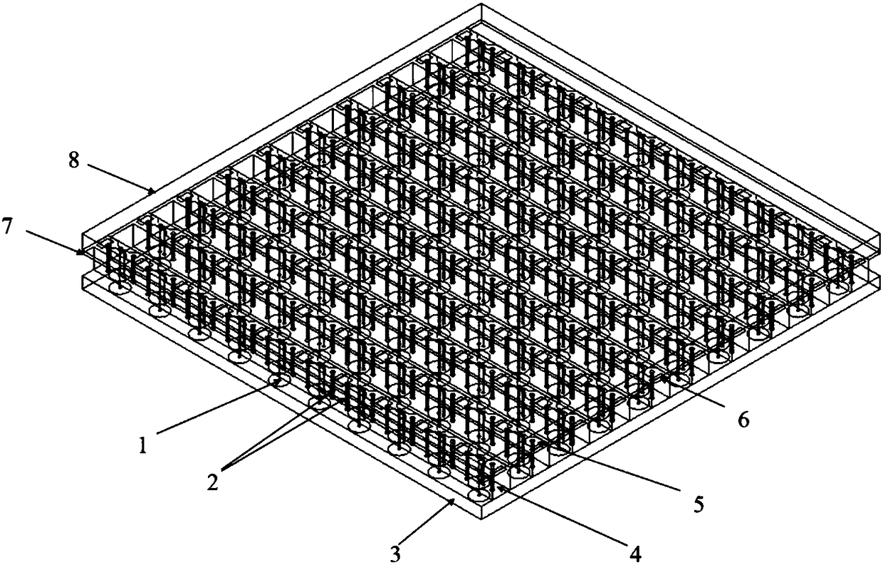
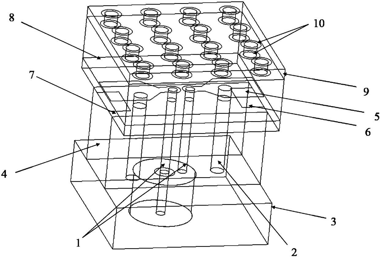
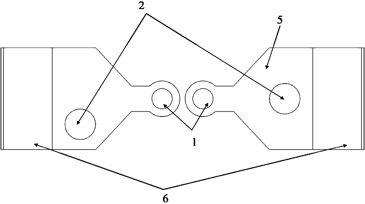
[0024] refer to Figure 1 to Figure 3 , Embodiment 1 consists of a layer of periodic structures printed with closely arranged dipole units, using periodic boundary conditions to simulate the simulation of the present invention in an infinite array environment. The antenna unit structure of the present invention is described as follows: the unbalanced feeding structure of the antenna; two grounded metallized through holes; the aluminum material floor (3) with a certain thickness; the dielectric substrate for supporting the whole phased array antenna system structure (4); a printed dipole antenna unit with a strong capacitive coupling structure (5); a rectangular patch (6) for strengthening the capacitive coupling at the end of the antenna unit; a dielectric layer (7) carrying a printed patch; the first layer A wide-angle impedance matching layer (8); a second wide-angle impedance matching layer (9); and a metal periodic structure (10) on the second wide-angle impedance matching...

Embodiment 2

[0028] specifically. Each antenna element (such as figure 2 shown) respectively extend along the two-dimensional direction of the array, which can constitute figure 1 The 10×10 low RCS low profile wide bandwidth angular scanning phased array antenna. Other structures are the same as those in Embodiment 1, and will not be repeated here.

[0029] Figure 8 to Figure 1 0 gives the scattering characteristics and radiation pattern of this example 2. Figure 8 Specific example 2 is given, and example 2 does not have two layers of wide-angle impedance matching layers and the same large-area metal floor. The comparison chart of single-station RCS results when co-polarized waves are vertically incident, it can be seen that this implementation The phased array developed in Example 2 has good low RCS characteristics. Figure 9 It is a comparison chart of the single-station RCS results of the specific embodiment 2 and the reference antenna (a Vivaldi antenna array with the same oper...


PUM


Abstract

The invention discloses an improved-type low-profile low-scattering strong-coupling UWB (ultra wide band) phased array, and the phased array comprises a series of dipole radiation unit layers which are regularly and periodically printed on one thin dielectric layer. A rectangular paste placed below a dipole antenna unit in each radiation unit layer can improve the capacity coupling of the tail endof the antenna unit. A metal periodic structure is added to a second wide angle impedance matching layer of the antenna, and the asymmetric processing of two grounded metalized through holes is performed. The above measures can effectively improve the unit active standing-wave ratio during H plane scanning, and effectively inhibit the mode item scanning. The second wide angle impedance matching layer can effectively reduce the single-station RCS during the vertical incidence of co-polarized waves. The antenna provided by the invention is especially suitable for a hidden carrier platform in anew generation.

Description

technical field [0001] The invention belongs to the technical field of antenna engineering, and in particular relates to a low-profile broadband phased antenna array system with low scattering characteristics. Controlled antenna array, especially suitable for the new generation of stealth carrier platform. Background technique [0002] The phased array antenna is composed of many antenna elements. When the phase shifter is used to feed these elements with variable phase, it can realize fast beam scanning of nanosecond level. Moreover, compared with the traditional mechanical beam scanning system, the phased array antenna has a very low time delay and has no shortcomings such as motion inertia and mechanical vibration, so it is widely used in the fields of target detection, tracking, imaging, and satellite communication. In the traditional phased array antenna design, on the one hand, it is necessary to design a broadband antenna element whose element size is smaller than ha...

Claims


Application Information

Patent Timeline
IPC IPC(8): H01Q21/06H01Q1/38H01Q1/50
Inventor 杨仕文黄健辉陈晨杨沛吉屈世伟陈益凯
Owner UNIV OF ELECTRONIC SCI & TECH OF CHINA
Why Eureka
Try Eureka