Device and method for detecting high-speed optical communication transmitting equipment
A technology of transmitting equipment and optical communication, applied in electromagnetic wave transmission systems, electrical components, transmission systems, etc., can solve the problems of opaque symbol rate of clock synchronization circuit, achieve the effect of convenient inspection of products, and reduce the difficulty and cost of implementation
- Summary
- Abstract
- Description
- Claims
- Application Information
AI Technical Summary
Problems solved by technology
Method used
Image
Examples
Embodiment 1
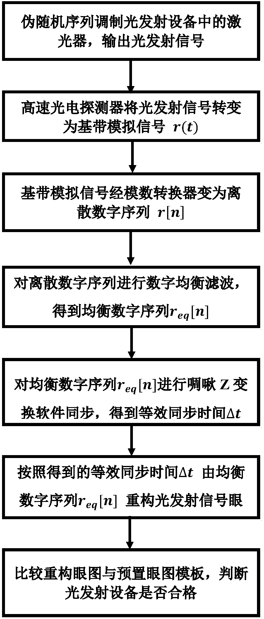
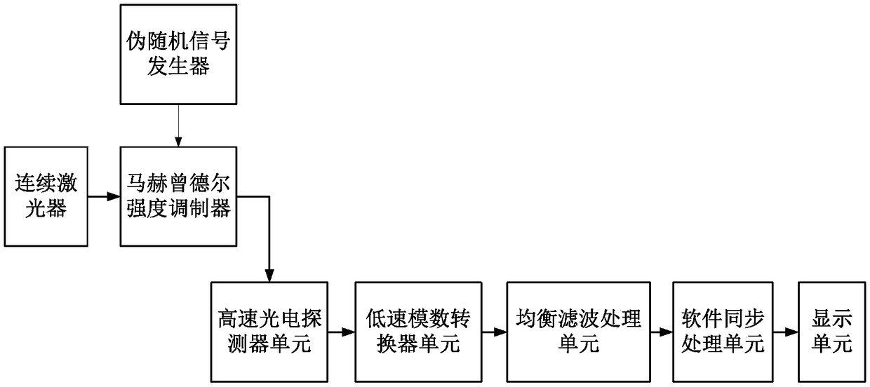
[0044] Embodiment 1 describes a device and method for detecting high-speed optical communication transmitting equipment of the present invention, the principle of detecting high-speed optical communication transmitting equipment, the composition and functions of the device. Such as figure 1 and figure 2As shown, the pseudo-random sequence modulates the laser in the optical transmission device to output the optical transmission signal, the high-speed photodetector converts the optical transmission signal output by the optical transmission device into a baseband analog electrical signal, and the low-speed analog-to-digital converter unit converts the baseband analog electrical signal Sampling to obtain a discrete digital sequence; and then through digital equalization and filtering to obtain a balanced digital sequence. The equalized digital sequence is processed synchronously by Chirp Z transform software to obtain its equivalent synchronous time. According to the equivalent...
Embodiment 2
[0046] This embodiment 2 describes the application of a device and method for detecting high-speed optical communication transmission equipment of the present invention to detect the eye diagram of a 10 Gbit / s optical transmission signal generated by an intensity-modulated optical transmitter. In this example, the experimental system such as image 3 As shown, a continuous laser, a Mach-Zehnder intensity modulator and a pseudo-random sequence generator simulate optical communication transmitting equipment: the optical power of the laser is 3.0dBm, and the pseudo-random sequence generator generates a pseudo-random sequence with a rate of 10Gbit / s. After shaping and amplifying, the Mach-Zehnder intensity modulator is driven to modulate the intensity of the continuous laser and output the intensity-modulated light emission signal.
[0047] The bandwidth of the photodetector is 10GHz, and the sampling rate of the analog-to-digital converter is 80MHz. Such as Figure 4 As shown, ...
Embodiment 3
[0049] This embodiment 3 describes the application of a device and method for detecting high-speed optical communication transmission equipment of the present invention to detect the eye diagram and constellation of the 10G baud QPSK optical transmission signal produced by the optical transmitter modulated by quaternary phase shift keying (QPSK) picture. In this example, the experimental system such as Figure 6 As shown, the continuous laser, the I-Q modulator and the arbitrary waveform generator simulate the QPSK modulation format optical communication transmitting equipment: the optical power of the laser is 3.0dBm, the arbitrary waveform generator generates a pseudo-random sequence with a rate of 10G baud, after pulse shaping and Amplified to drive the I-Q modulator. The I-channel modulator and the Q-channel modulator generate two binary phase-shift keying optical signals respectively. Adjust the phases of the I-way modulator and the Q-way modulator so that the two-way m...
PUM
 Abstract
Description
Claims
Application Information
 - R&D
- Intellectual Property
- Life Sciences
- Materials
- Tech Scout
- Unparalleled Data Quality
- Higher Quality Content
- 60% Fewer Hallucinations
Browse by: Latest US Patents, China's latest patents, Technical Efficacy Thesaurus, Application Domain, Technology Topic, Popular Technical Reports.
© 2025 PatSnap. All rights reserved.Legal|Privacy policy|Modern Slavery Act Transparency Statement|Sitemap|About US| Contact US: help@patsnap.com


