Wet desulfurization flue gas gypsum rain eliminating system and wet desulfurization flue gas gypsum rain eliminating method

A wet desulfurization and flue gas technology, which is applied in the field of wet desulfurization flue gas whitening system, can solve the problems of bulky flue gas heating heat exchanger, large heat load of flue gas heating heat exchanger, and total sulfur-containing emissions. It can improve the overall reliability and economy, reduce the content of saturated steam and liquid water, and reduce the content of gypsum particles.

Pending Publication Date: 2018-09-07
TIANJIN HUASAIER HEAT TRANSFER EQUIP
View PDF0 Cites 5 Cited by
  • Summary
  • Abstract
  • Description
  • Claims
  • Application Information

AI Technical Summary

Problems solved by technology

[0006] (2) The desulfurization flue gas outlet has a large moisture content, which entrains gypsum particles. During the discharge process, the temperature of the flue gas decreases, and the water in the flue gas precipitates, forming phenomena such as "gypsum rain" and "white fog" around the chimney, causing unpleasant Necessary economic loss and environmental concerns
[0008] (1) The actual total amount of sulfur-containing emissions has not been reduced, and the pollution to the environm

Method used


Image

  • Wet desulfurization flue gas gypsum rain eliminating system and wet desulfurization flue gas gypsum rain eliminating method
  • Wet desulfurization flue gas gypsum rain eliminating system and wet desulfurization flue gas gypsum rain eliminating method
  • Wet desulfurization flue gas gypsum rain eliminating system and wet desulfurization flue gas gypsum rain eliminating method

Examples


Embodiment Construction

[0047] In order to enable those skilled in the art to better understand the technical solutions of the present invention, the present invention will be further described in detail below in conjunction with the accompanying drawings and preferred embodiments.

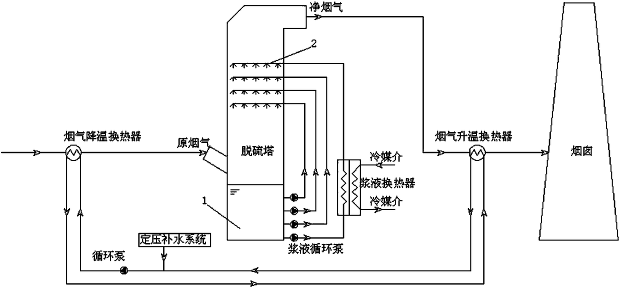
[0048] Such as figure 1 As shown, the present invention includes a flue gas cooling heat exchanger, a desulfurization tower, a flue gas heating heat exchanger and a chimney through which the flue gas passes sequentially, wherein,

[0049] A heat medium water circulation loop is provided between the flue gas cooling heat exchanger and the flue gas heating heat exchanger, the cold source medium channel of the flue gas cooling heat exchanger passes through the heat medium water, and the heat source of the flue gas cooling heat exchanger The medium channel passes through the flue gas; the heat source medium channel of the flue gas heating heat exchanger passes through the heat medium water, the cold source medium channel of ...


PUM


Abstract

The invention provides a wet desulfurization flue gas gypsum rain eliminating system and a wet desulfurization flue gas gypsum rain eliminating method, and relates to a flue gas desulfurization and flue gas gypsum rain eliminating system and a flue gas desulfurization and flue gas gypsum rain eliminating method. The wet desulfurization flue gas gypsum rain eliminating system comprises a flue gas cooling heat exchanger, a desulfurization tower equipped with a slurry cooler, a flue gas heating heat transfer and a heat medium water circulation system. According to the wet desulfurization flue gasgypsum rain eliminating system, in the flue gas cooling heat exchanger, heat medium water recovers the waste heat of the flue gas and reduces the temperature of the flue gas, wherein the cooled fluegas can improve the dust removal and desulfurization efficiency; in the slurry cooler, the desulfurization slurry is cooled, and the cooled slurry is used for the wet removal and desulfurization of the flue gas; and in the flue gas heating heat exchanger, the heat medium water recovering the waste heat of the flue gas heats the desulfurized flue gas so as to increase the superheat degree. With thesystem and the method of the present invention, the desulfurization efficiency is improved while the flue gas gypsum rain is eliminated, and the investment on the whole desulfurization process systemis reduced.

Description

technical field [0001] The invention relates to the application field of flue gas desulfurization, in particular to a flue gas whitening system and method for wet desulfurization. Background technique [0002] With the implementation of the "Emission Standard of Air Pollutants for Thermal Power Plants" (GB13226-2011) promulgated by the Ministry of Environmental Protection, it is required that the soot emission standard for coal-fired boilers should reach 30mg / Nm 3 , SO 2 The content is controlled at 100mg / m according to the difference between new and existing power plants 3 , 200mg / m 3 , soot and SO in key areas in the future 2 Emissions are controlled at 20mg / m3, 50mg / m3 3 . The increasingly stringent emission standards of air pollutants force coal-fired power plants and other coal-fired boiler enterprises to modify the flue gas emission system to meet the ultra-clean emission requirements. [0003] Coal-fired boilers use coal as energy, and produce a large amount of ...

Claims


Application Information

Patent Timeline
IPC IPC(8): B01D53/80B01D53/50B01D53/26F23J15/06F23J15/02
CPCB01D53/265B01D53/502B01D53/504F23J15/022F23J15/06B01D2258/0283Y02E20/30
Inventor 宋秉棠赵殿金
Owner TIANJIN HUASAIER HEAT TRANSFER EQUIP
Why Eureka
Try Eureka