
Capacitor guide pin and manufacturing method thereof

A capacitor and guide needle technology, applied in the direction of capacitor manufacturing, capacitors, capacitor terminals, etc., can solve the problems of the size of the explosion point, the appearance is difficult to control, the incision has burrs and acute angles, and the plastic sleeve is punctured and cracked, and the structure is simple and reasonable. , High bending strength, and the effect of improving product quality

Pending Publication Date: 2018-09-07
NANTONG NANMING ELECTRONICS
View PDF0 Cites 4 Cited by
  • Summary
  • Abstract
  • Description
  • Claims
  • Application Information

AI Technical Summary

Problems solved by technology

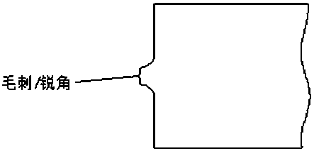
[0005] Tinned copper-clad steel wire section, one end is welded with aluminum wire to form a welding point, the size and appearance of the welding point are limited by the aperture size and thickness of the rubber plug of the capacitor, because the welding is performed under normal conditions, oxygen in the air will produce gas Explosion, the size and appearance of the burst point are difficult to control, resulting in the phenomenon that the rubber in the hole is punctured or exposed after the rubber plug is inserted (see figure 1 ); the other end of the tinned copper-clad steel wire has burrs and sharp angles due to the cut (see figure 2 ), after the capacitor is covered with a plastic sleeve in the post-processing process, the friction between the terminal and the capacitor will puncture and crack the plastic sleeve (see figure 1 )

Method used


Image

  • Capacitor guide pin and manufacturing method thereof
  • Capacitor guide pin and manufacturing method thereof
  • Capacitor guide pin and manufacturing method thereof

Examples


Embodiment 1

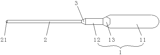
[0027] see image 3 , a capacitor guide pin, which are respectively a positive guide pin and a negative guide pin. The positive guide pin is 5-8mm longer than the negative guide pin. Composed of steel-clad wire 2, part of the aluminum wire 1 is stamped to form a flat head 11 with a thickness of 0.2-0.3mm, and the other part is a cylinder 12 with a diameter of 1.0-2.5mm, and the cylinder 12 is located in the flat On the transverse centerline of the flat head 11, a transition part 13 is formed between the flat head 11 and the cylinder 12, the transition part 13 is square R-shaped, and the length is 1.0-1.3mm, and the maximum width is 1.0-1.5mm. The transition part 13 is in the shape of a square R, which has high bending strength and can withstand three times of 90° bending with a load of 800g to avoid damage and breakage during container assembly; the flat head 11 is an arc-shaped structure; tin-plated The copper-clad steel wire 2 is welded to the cylinder 12 of the aluminum wi...

Embodiment 2

[0028] Embodiment 2, in order to reduce the probability of internal piercing of the pole foil and improve product quality, the flat head 11 has an arc-shaped structure, and the radius of the front end of the flat head 11 is 1 / 2 of the width of the flat head 11 one.

Embodiment 3

[0029] Embodiment 3, in order to enable the size and appearance of the solder joint 3 to be well controlled, to avoid the rubber plug being inserted into the hole or to expose the rubber, the length of the solder joint 3 should be controlled between 0.5-0.8 mm, and The outer diameter of the welding spot 3 is smaller than or equal to the diameter of the aluminum wire 1 . .

[0030] It also includes the manufacturing method of the capacitor guide pin, which respectively undergoes stamping, sharp angle removal, welding and electrochemical deburring, and the specific steps are as follows:

[0031] Stamping forming: a part of the aluminum wire is stamped to form a flat head with a thickness of 0.2-0.3mm, and the other part is not stamped and is a cylinder with a diameter of 1.0-2.5mm, and the cylinder is located in the flat head On the transverse center line of 11, a transition part is formed between the flat head and the cylinder, the transition part is in the shape of a square R...


PUM

PropertyMeasurementUnit
thicknessaaaaaaaaaa
diameteraaaaaaaaaa
lengthaaaaaaaaaa

Abstract

The invention discloses a capacitor guide pin and a manufacturing method thereof. The capacitor guide pin is composed of an aluminum wire and a tin-plated copper-clad steel wire. A part of the aluminum wire is punched to form a flat head, and another part of the aluminum wire is a cylinder located at the transverse center line of the flat head. A transitional portion is formed between the flat head and the cylinder and is in a square R shape. The flat head is an arc structure. The tin-plated copper-clad steel wire and the cylinder of the aluminum wire are soldered and have a solder joint therebetween in a truncated cone shape. The front end surface of the tin-plated copper-clad steel wire is a circular arc end face, and has a radius of a half of the diameter of the tin-plated copper-clad steel wire. The transitional portion is in a square R shape and has large bending strength so as to avoid damage and fracture during the assembly of a container. The flat head is an arc structure so asto reduce the probability of piercing the inner foil and improve product quality. The size and the appearance of the solder joint can be well controlled to avoid puncturing the rubber in the apertureor exposure after a rubber plug is inserted.

Description

technical field [0001] The invention relates to the technical field of capacitor components, in particular to a capacitor guide pin and a manufacturing method. Background technique [0002] In the application, the capacitor has two guide pins as the signal source, and its guide pin function consists of two parts, namely internal connection and external connection. The guide pin material consists of two parts: aluminum wire and tinned copper-clad steel wire. After welding by arc welding, a part of the aluminum wire is stamped and deformed, and the required shape and size are obtained through the mold. The deformed part is in the shape of a rectangle. One part is not stamped and remains cylindrical. [0003] The internal connection of the guide pin is a rectangular thin sheet connected with the capacitor foil by cold pressing method, and then wound with insulating paper to form a core; the external connection of the guide pin is mainly that the tinned copper-clad steel wire p...

Claims


Application Information

Patent Timeline
Patent Type & Authority Applications(China)
IPC IPC(8): H01G9/008H01G13/00B23P15/00
CPCH01G9/008H01G13/00B23P15/00
Inventor 印斌吴亮成冯莉孙书婷田斌杨国华
Owner NANTONG NANMING ELECTRONICS
Learn More