Micro robot driven by point light source and preparation method thereof

A micro-robot, point light source technology, applied in micro-manipulators, chemical instruments and methods, manipulators, etc., can solve the problems of limited material microstructure, low controllability, limited control accuracy of light-driven microrobots, etc. Effects of heat conversion efficiency, high environmental compatibility

Active Publication Date: 2018-09-14
FUDAN UNIV
View PDF6 Cites 14 Cited by
  • Summary
  • Abstract
  • Description
  • Claims
  • Application Information

AI Technical Summary

Problems solved by technology

However, the light-to-heat conversion materials currently used are limited by the microstructure of the material and cannot achieve directional heat transfer, which means that the light energy input into the system cannot be directly transmitted to the liquid surface to form a thrust to drive the micro-robot
In addition, the inability of directional heat transfer in existing photothermal conversion materials also leads to low controllability of the surface tension gradient produced by light-driven micro-robots on the liquid surface, which greatly affects the fixed-point thrust of light-driven micro-robots The emergence of light-driven micro-robots limits the control accuracy and reduces the energy conversion efficiency and practical application value of the entire drive system.

Method used


Image

  • Micro robot driven by point light source and preparation method thereof
  • Micro robot driven by point light source and preparation method thereof
  • Micro robot driven by point light source and preparation method thereof

Examples


Embodiment 1

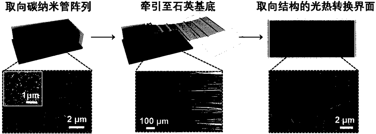
[0027] (1) Preparation of aligned carbon nanotube light-absorbing material: Prepare a transparent quartz plate with a length of 4 mm, a width of 8 mm, and a thickness of 0.05 mm as a substrate; prepare a spinnable carbon nanotube array by chemical vapor deposition, and use a blade to form a carbon nanotube Pull a carbon nanotube film with a width of 3 mm on one side of the array, and overlap 20 layers on the quartz plate to obtain an aligned carbon nanotube film with a thickness of 200 μm, whose orientation direction is consistent with the pulling direction and perpendicular to the long side of the quartz plate;

[0028] (2) Preparation of light-to-heat conversion interface based on aligned carbon nanotubes: Add 10 microliters of ethanol dropwise around the composite sheet of quartz sheet / aligned carbon nanotubes to make the aligned carbon nanotube film and the quartz sheet fit closely, and heat at 50°C For 1 minute, the ethanol was partially evaporated to dryness; cut off alon...

Embodiment 2

[0033] (1) Preparation of aligned carbon nanotube light-absorbing material: Prepare a transparent quartz plate with a length of 6 mm, a width of 9 mm, and a thickness of 0.1 mm as a substrate; prepare a spinnable carbon nanotube array by chemical vapor deposition, and use a blade to form a carbon nanotube Pull a carbon nanotube film with a width of 5 mm on one side of the array, and overlap 30 layers on the quartz plate to obtain an aligned carbon nanotube film with a thickness of 500 μm, whose orientation direction is consistent with the pulling direction and perpendicular to the long side of the quartz plate;

[0034] (2) Preparation of a light-to-heat conversion interface based on aligned carbon nanotubes: Add 50 microliters of ethanol dropwise around the composite sheet of quartz sheet / aligned carbon nanotubes to make the aligned carbon nanotube film and the quartz sheet fit closely, and heat at 60°C After 3 minutes, the ethanol was partially evaporated to dryness; the quar...

Embodiment 3

[0040] (1) Preparation of aligned carbon nanotube light-absorbing material: Prepare a transparent quartz plate with a length of 8 mm, a width of 10 mm, and a thickness of 0.2 mm as the substrate; prepare a spinnable carbon nanotube array by chemical vapor deposition, and use a blade to form a carbon nanotube Pull a carbon nanotube film with a width of 7 mm on one side of the array, and overlap 50 layers on the quartz plate to obtain an aligned carbon nanotube film with a thickness of 1000 μm, whose orientation direction is consistent with the pulling direction and perpendicular to the long side of the quartz plate;

[0041] (2) Preparation of a light-to-heat conversion interface based on aligned carbon nanotubes: Add 100 microliters of ethanol dropwise around the quartz sheet / aligned carbon nanotube composite sheet to make the aligned carbon nanotube film and the quartz sheet tightly bonded, and heat at 80°C After 5 minutes, the ethanol was partially evaporated to dryness; the ...


PUM

PropertyMeasurementUnit
wavelengthaaaaaaaaaa
thicknessaaaaaaaaaa
thicknessaaaaaaaaaa

Abstract

The invention belongs to the technical field of micro robots, and particularly relates to a micro robot driven by a point light source. The micro robot is formed by assembling a photo-thermal conversion interface which is an oriented carbon nanotube and a flexible and transparent base prepared from polydimethylsiloxane; when a light spot is controlled to irradiate on the photo-thermal conversion interface, photo-thermal conversion is generated in the structure of the carbon nanotube, and the generated heat is conducted to a floating liquid surface where the whole micro robot floats along a vertical oriented structure of the carbon nanotube; according to the Marangoni effect, the surface tension of the heated liquid surface adjacent to the photo-thermal conversion interface is sharply reduced, and the surface tension difference is formed between the heated liquid surface and the surrounding non-heated liquid surface, so that asymmetric pushing force is generated on the whole micro robot, and the micro robot is driven to move on the liquid surface. The micro robot has relatively high environmental adaptability and high controllability, and by setting different light-driven response interface distribution and point light source movement tracks, micro wireless remote driving systems with different motion modes can be obtained according to actual application scenes.

Description

technical field [0001] The invention belongs to the technical field of micro-robots, and in particular relates to a micro-robot and a preparation method thereof. Background technique [0002] Micro-robots have attracted extensive attention from academia and industry in recent years because of their application potential to perform controllable movements and complete specific tasks in small spaces or microscopic scales. Among many energy supply systems for micro-robots, the optical drive mechanism has become one of the most feasible and most suitable means for precisely controlling the motion of micro-robots because it does not require a medium for transmission and the light source switch is easy to realize. The photothermal effect is an efficient light energy driving mechanism. Its principle is to convert the light energy input at a specific position into heat energy through the photothermal conversion material, and use the generated heat energy to generate a thermally induc...

Claims


Application Information

Patent Timeline
Patent Type & Authority Applications(China)
IPC IPC(8): B25J7/00C09K3/00C01B32/16C01B32/168
CPCB25J7/00C01B2202/06C01B2202/20C09K3/00C01B32/16C01B32/168
Inventor 廖萌叶蕾李陟彭慧胜
Owner FUDAN UNIV
Why Eureka
Try Eureka