Dynamic comparator

A dynamic comparator and latch technology, applied in instruments, amplifiers, differential amplifiers, etc., can solve the problems of inapplicable wide common-mode input voltage range, large voltage margin, design circuits, etc., to achieve low offset voltage, reduce Power consumption, offset reduction effect

Inactive Publication Date: 2018-09-14
INST OF MICROELECTRONICS CHINESE ACAD OF SCI
View PDF5 Cites 18 Cited by
  • Summary
  • Abstract
  • Description
  • Claims
  • Application Information

AI Technical Summary

Problems solved by technology

[0004] However, the traditional dynamic comparator with latch structure needs a large voltage margin, which is not conducive to the design of circuits in low-voltage deep submicron CMOS technology, and the delay and offset of this structure are very affected by the change of common-mode input voltage. , this feature makes traditional latch structure dynamic comparators unsuitable for wide common-mode input voltage range applications

Method used


Image

  • Dynamic comparator
  • Dynamic comparator
  • Dynamic comparator

Examples


Embodiment Construction

[0031] In order to make the purpose, technical solutions and advantages of the embodiments of the present invention clearer, the technical solutions in the embodiments of the present invention will be clearly and completely described below in conjunction with the drawings in the embodiments of the present invention. Obviously, the described embodiments It is only some embodiments of the present invention, but not all embodiments. Based on the embodiments of the present invention, all other embodiments obtained by persons of ordinary skill in the art without making creative efforts belong to the protection scope of the present invention.

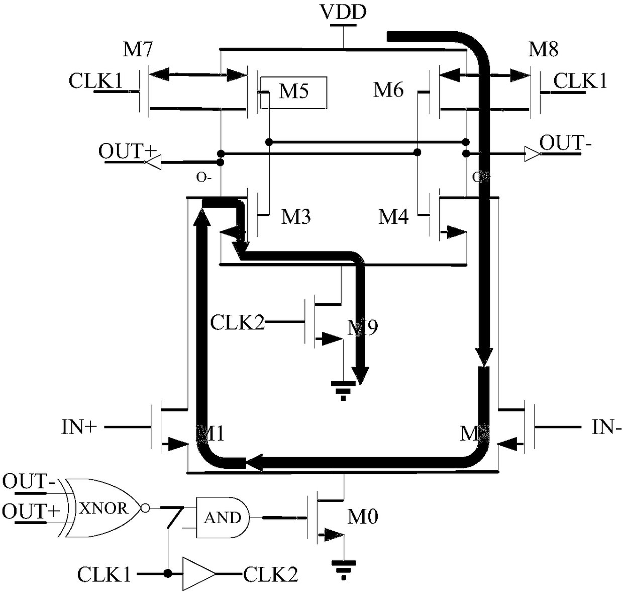
[0032] We first introduce the hidden quiescent current paths that common dynamic comparators have. Such as figure 1 As shown, it is a schematic diagram of the structure of an ordinary dynamic comparator with a hidden static current path. Assuming that the input signal IN+ is greater than IN-, in the latching stage, the transistors M4, M5, M7...


PUM


Abstract

The invention discloses a dynamic comparator. The dynamic comparator comprises a pre-amplifier and a positive feedback latch, wherein the pre-amplifier is controlled by a clock signal CLK1 and outputsignals OUT+ and OUT- of a comparator; the positive feedback latch is controlled by a clock signal CLK2; when the CLK1 and the CLK2 are at a low level, a tail current tube of the pre-amplifier and a tail current tube of the positive feedback latch are both in a cut-off state, two switch tubes of the positive feedback latch enter a conductive state, two outputs of the latch reach a power voltage, the latch enters a reset stage, and two switch tubes of the pre-amplifier are controlled by the OUT+ and the OUT- to enter a conductive state; and when the signal CLK1 and the signal CLK2 sequentiallyreach a high level, the tail current tube of the pre-amplifier and the tail current tube of the positive feedback latch both enter a conductive state, the pre-amplifier works in an amplification state, amplifies an input signal and sends the amplified input signal to a latch node of the latch, the positive feedback latch works and outputs a comparison result, and after the two output signals OUT+and OUT- of the comparator pass through inverters, either of the two output signals increases and controls the corresponding switch tube (M3 or M4) of the pre-amplifier to enter a cut-off state, so that a path is cut off.

Description

technical field [0001] The invention relates to the technical field of analog-to-digital conversion, in particular to a dynamic comparator. Background technique [0002] The high-speed low-power comparator is an important part of the high-performance analog-to-digital converter (ADC). The power consumption, offset, delay and other indicators of the comparator also affect the performance of the entire circuit within a certain range. However, with the continuous reduction of process size, the power supply voltage and device threshold voltage have not decreased synchronously, which brings challenges to the design of high-performance comparators. [0003] Commonly used comparators include static comparators and dynamic comparators. The offset voltage and noise of the static comparator are small, but due to the static current in the pre-amplifier and the latch, the general power consumption is relatively large, and the typical static comparator has a static DC current at the out...

Claims


Application Information

Patent Timeline
Patent Type & Authority Applications(China)
IPC IPC(8): H03M1/06H03M1/00H03K5/22H03F3/45
CPCH03F3/45197H03K5/22H03M1/002H03M1/06
Inventor 周万兴王云峰刘昱
Owner INST OF MICROELECTRONICS CHINESE ACAD OF SCI
Why Eureka
Try Eureka