Target module and machining method

A processing method and target technology, applied in the field of mechanical processing, can solve the problems of target sputtering performance degradation, target deformation, expansion, etc., and achieve the effect of improving sputtering performance and quality

Active Publication Date: 2018-09-28
KONFOONG MATERIALS INTERNATIONAL CO LTD
View PDF7 Cites 7 Cited by
  • Summary
  • Abstract
  • Description
  • Claims
  • Application Information

AI Technical Summary

Problems solved by technology

However, in the prior art, after the target and the back plate are welded, obvious weld seams are easily left at the joint position. During the sputtering process of the target, the remaining weld seams will affect the air flow direction on the surface of the target component. , leading to a decrease in the sputtering performance of the target, and at the same time, in the subsequent processing of the target assembly, the residual weld seam may further expand, resulting in serious quality problems such as target deformation

Method used


Image

  • Target module and machining method
  • Target module and machining method
  • Target module and machining method

Examples


no. 1 example

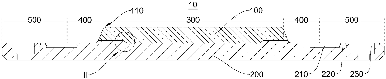
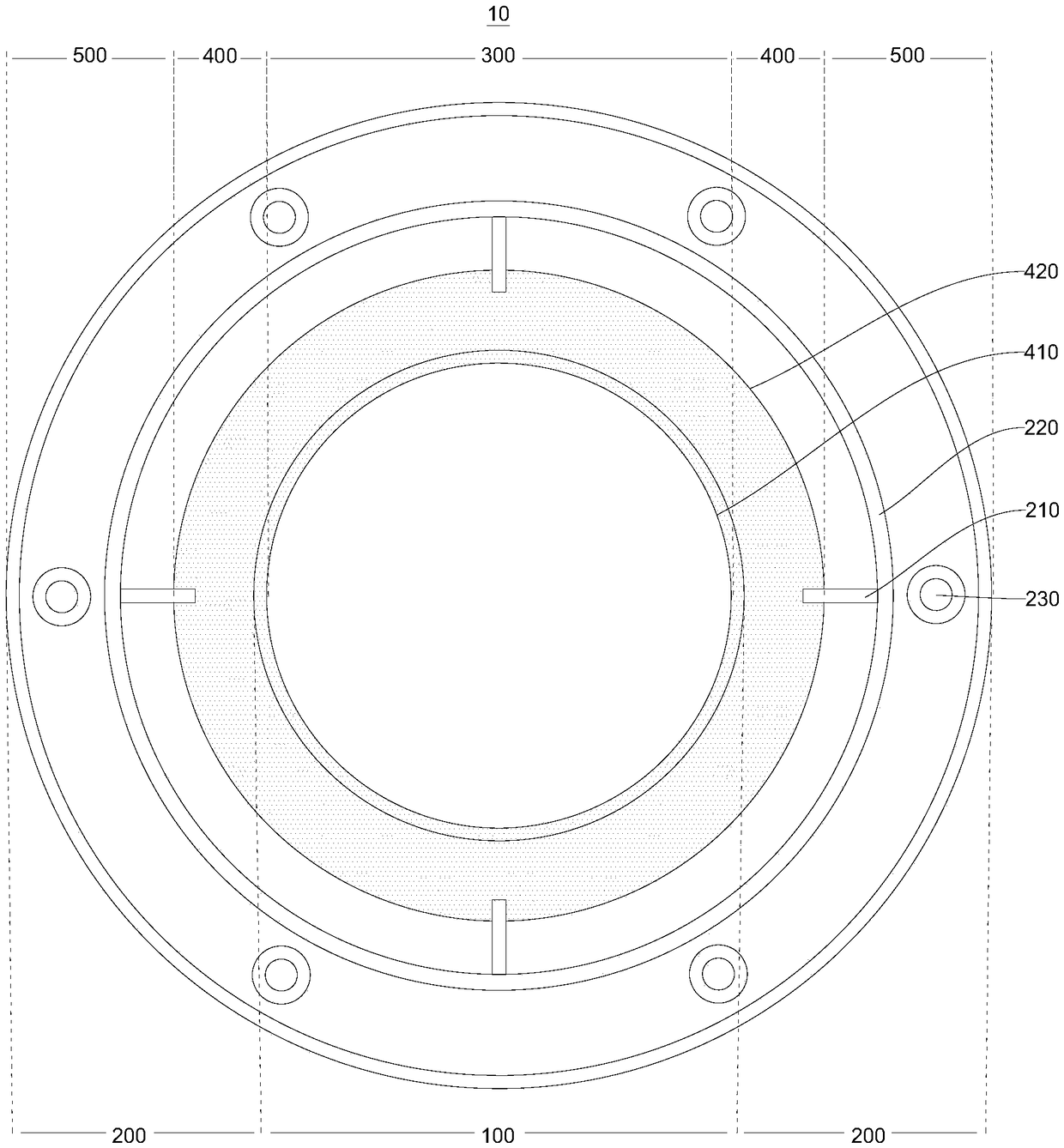
[0044] figure 1 A schematic structural view of the target assembly 10 provided by the embodiment of the present invention under a first viewing angle is shown. figure 2 A schematic structural view of the target assembly 10 provided by the embodiment of the present invention under the second viewing angle is shown. The target assembly 10 is used for sputtering coating in the semiconductor chip manufacturing process. combined reference figure 1 as well as figure 2 , the target assembly 10 includes a target 100 and a back plate 200 for carrying the target 100 . The target assembly 10 is usually made of metal, alloy, ceramics and other materials. For example, the target 100 is made of titanium, and the back plate 200 is made of aluminum. Of course, this is only a relatively common combination of materials. The target 100 and The backplane 200 can also use other combinations of materials.

[0045] Wherein, the surface of the target 100 includes a front side and a back side o...

no. 2 example

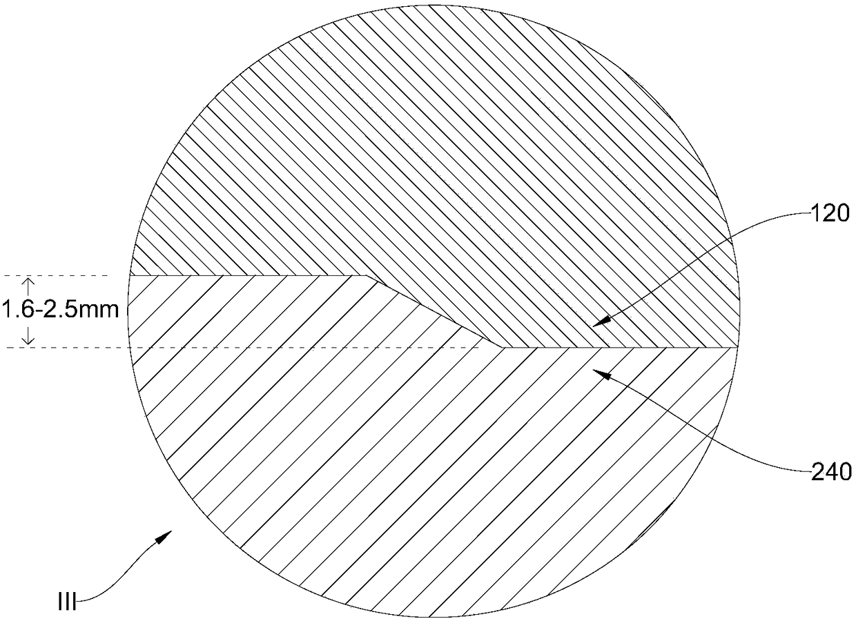
[0063] The embodiment of the present invention also provides a target assembly processing method for processing the target assembly 10 provided in the embodiment of the present invention, the method includes: turning a second surface protruding from the back of the target 100 on the back of the target 100 A step 120, the side of the first step 120 is a bevel; on the front of the back plate 200, according to the shape matching with the first step 120, the first groove 240 recessed in the front of the back plate 200 is turned; the first step 120 embedded in the first groove 240, and connect the back of the target 100 and the front of the back plate 200 together by diffusion welding.

[0064] The implementation principles and technical effects of the above methods have been described in the aforementioned product examples. For a brief description, for the parts not mentioned in the method examples, you can refer to the corresponding content in the aforementioned product examples. ...


PUM


Abstract

The invention relates to the technical field of machining, and provides a target module and a machining method. The target module comprises a target and a back plate for bearing the target. The surface of the target comprises a front surface and a back surface; the front surface of the target is a sputtering surface of the target; the back surface of the target is opposite to the front surface ofthe target; a first step is projected on the back surface of the target; and the side surface of the first step is an inclined surface. A first groove matched with the first step is formed in the front surface of the back plate; the back surface of the target and the front surface of the back plate are connected through dispersion welding; and the first step is embedded in the first groove. In thedispersion welding process, the back surface of the target is tightly bonded with the front surface of the back plate; and a finally molded target module generates no welding line in the joint position of the two, so that the sputtering performance of the target can be improved, meanwhile, the problem related to the welding line cannot occur in subsequent machining process of the target module, and the quality of the produced target module is improved.

Description

technical field [0001] The invention relates to the field of mechanical processing, in particular to a target component and a processing method. Background technique [0002] Diffusion welding refers to a solid-state welding method that pressurizes workpieces at high temperatures without visible deformation and relative movement. Diffusion welding is especially suitable for the joining of new materials such as dissimilar metal materials, heat-resistant alloys and ceramics, intermetallic compounds, and composite materials. During the processing of the target assembly, the target and backing plate are usually welded together by diffusion welding. However, in the prior art, after the target and the back plate are welded, obvious weld seams are easily left at the joint position. During the sputtering process of the target, the remaining weld seams will affect the air flow direction on the surface of the target component. , leading to a decrease in the sputtering performance of...

Claims


Application Information

Patent Timeline
Patent Type & Authority Applications(China)
IPC IPC(8): B23K20/02B23K20/26
CPCB23K20/026B23K20/26
Inventor 姚力军潘杰王学泽张良进
Owner KONFOONG MATERIALS INTERNATIONAL CO LTD
Why Eureka
Try Eureka