High-reflectivity material surface defect thermal imaging detection system and method

A technology of high reflectivity and detection system, applied in the field of detection, can solve the problems of time-consuming, light pollution of the inspectors, and slow detection speed, and achieve the effect of avoiding light pollution, fast inspection speed and high accuracy.

Active Publication Date: 2018-09-28
HUNAN UNIV
View PDF6 Cites 4 Cited by
  • Summary
  • Abstract
  • Description
  • Claims
  • Application Information

AI Technical Summary

Problems solved by technology

Infrared thermal imaging detection method generally adopts light excitation as the detection excitation method for surface cracks of high-reflectivity materials, and light excitation causes light pollution to inspectors, especially halogen lamps, flash lamps and laser excitation must take protective measures, and at the same time Part of the energy needs to be supplied to the excitation source, and the excitation process takes time and the detection speed is slow

Method used


Image

  • High-reflectivity material surface defect thermal imaging detection system and method
  • High-reflectivity material surface defect thermal imaging detection system and method
  • High-reflectivity material surface defect thermal imaging detection system and method

Examples


Embodiment 1

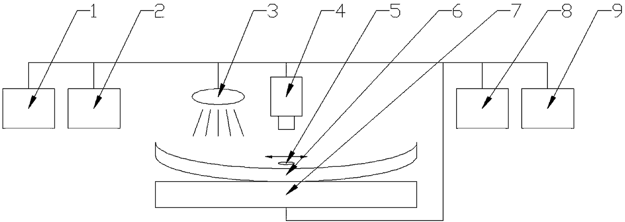
[0026] figure 1 As shown, a passive thermal imaging detection system for surface defects of high-reflectivity materials, the measured object 6 is an object with high surface reflectivity, which can be a high-reflectivity object of any shape and size. The detection system includes a parameter detection module 3, a system control module 1, an infrared measurement imaging module 4, a focus flag 5, a focus flag production module 2, a motion control module 7, a signal processing module 8 and a diagnosis module 9, and the system control module 1 can Use a computer.

[0027] The system control module 1 controls the laser scanning array or 3D scanner in the parameter detection module 3 to work to obtain the morphological parameters of the measured object 6, such as curvature, etc., and controls the triggering, disconnection, and working time of the infrared measurement imaging module 4, and The focus flag making module 2 makes the focus flag 5 and the linkage of other related modules...

Embodiment 2

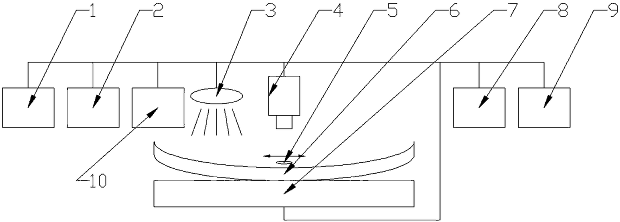
[0047] figure 2 As shown, an active thermal imaging detection system for surface defects of high-reflectivity materials, in order to further improve the detection signal-to-noise ratio, different excitation methods can be adopted to improve the detection effect, so the system can be added to the excitation module 10, the excitation module 10 It can be halogen lamp, flash lamp, laser, electromagnetic induction, electric current or ultrasonic, etc. The principle is: use these excitation modules 10 to give an excitation to the measured object 6, so that the measured object 6 has heat injection, and the defect position causes the surface heat distribution to be abnormal, and the defect parameters are inverted by observing the surface heat distribution.

[0048] A thermal imaging detection method for surface defects of high-reflectivity materials, using the above-mentioned detection system to perform intelligent detection of micro-crack defects on the surface of high-reflectivity ...


PUM


Abstract

The invention discloses a high-reflectivity material surface defect thermal imaging detection system and a high-reflectivity material surface defect thermal imaging detection method. The high-reflectivity material surface defect thermal imaging detection system comprises a parameter detection module, a system control module, an infrared measuring imaging module, a focusing flag, a focusing flag making module, a motion control module, a signal processing module and a diagnosis module. The high-reflectivity material surface defect thermal imaging detection system can detect fine crack defects onthe surface of a high-reflectivity material, is high in detection speed, simple in implementation, intuitive in result and high in efficiency, avoids radiation and chemical corrosion, avoids light pollution, saves energy, has high accuracy degree, can strictly control exposure and meets the requirement of the production process of special parts.

Description

technical field [0001] The invention belongs to the detection field, and in particular relates to a thermal imaging detection system and method for surface defects of high-reflectivity materials. Background technique [0002] In recent years, metal components have been widely used in petroleum, natural gas, chemical industry, shipbuilding, automobile and other industries; because these metal components may have voids, inclusions and initial damage in the process of processing and forming, and during transportation and use Due to various mechanical loads and temperature loads, new micro or macro damages will be produced on the surface, or affected by the corrosive medium in the working environment, it is very easy to have corrosive defects or micro damages on the inner and outer surfaces. , these opening cracks or near-surface cracks and micro-cracks are extremely harmful, while cracks hidden near the surface of materials and components are often the starting point of fatal c...

Claims


Application Information

Patent Timeline
Patent Type & Authority Applications(China)
IPC IPC(8): G01N25/72
CPCG01N25/72
Inventor 何赟泽王昵辰王洪金邓堡元
Owner HUNAN UNIV
Why Eureka
Try Eureka