

Iron core excitation device and method for seeking and recovering breakdown range of pouring coil
A technology of excitation device and excitation coil, applied in coil manufacturing, measurement device, transformer/inductor coil/winding/connection, etc., can solve the problems of broken transformer core, scrap, cumbersome, etc., to prevent material waste and reduce cumbersome process, the effect of improving the pass rate
- Summary
- Abstract
- Description
- Claims
- Application Information
AI Technical Summary
Problems solved by technology
Method used
Image

Examples
Embodiment
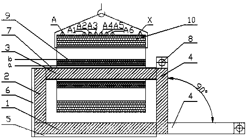
[0038] An iron core excitation device, which replaces the original transformer core, is composed of four square cross-sections, the first iron core column 1, the second iron core column 2, the third iron core column 3, and the movable iron core column 4 to form a closed magnetic circuit. With the base clip 5, the second clip 6, the latitude-free tape 7, the moving clip 8, and the excitation coil 9, an iron core excitation device is formed (see figure 1 ).
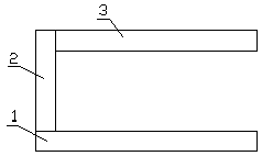
[0039] The overlap between the first core column 1, the second core column 2 and the third core column 3 is a right-angled seam that is repeatedly staggered and stacked into a "匚" shape (see figure 2 ), the first core column 1 is clamped with two base clamps 5 and used as a floor base; the second core column 2 is clamped with two second clamps 6; the third core column 3 is clamped with no weft The belt 7 is fastened and solidified into an integral structure; the movable core column 4 is clamped by a movable clamp 8 .
[...
PUM
 Abstract
Description
Claims
Application Information