
Multiferroic heterojunction and preparation method thereof

A technology of multiferroic heterojunction and ferroelectric layer, which is applied in the manufacture/processing of electromagnetic devices and the selection of materials, etc., can solve the problems of limited antiferromagnetic order and low temperature conditions due to the electric control magnetic effect, and achieve saving The effect of cumbersome processes

Inactive Publication Date: 2018-09-28
XIANGTAN UNIV
View PDF5 Cites 0 Cited by
  • Summary
  • Abstract
  • Description
  • Claims
  • Application Information

AI Technical Summary

Problems solved by technology

However, the electronically controlled magnetic effect realized in single-phase multiferroic materials is limited by its antiferromagnetic order and low temperature conditions, making its application in practical devices face great challenges.

Method used


Image

  • Multiferroic heterojunction and preparation method thereof
  • Multiferroic heterojunction and preparation method thereof
  • Multiferroic heterojunction and preparation method thereof

Examples


preparation example Construction

[0035] The present invention provides a method for preparing a multiferroic heterojunction described in the above technical solution, comprising the following steps:

[0036] Using STO as the target material, the first deposition is performed on the upper surface of the STO substrate by pulsed laser deposition to form the SRO bottom electrode layer;

[0037] Using BTO as a target, a second deposition is performed on the upper surface of the SRO bottom electrode layer by a pulsed laser deposition method to form a BTO ferroelectric layer;

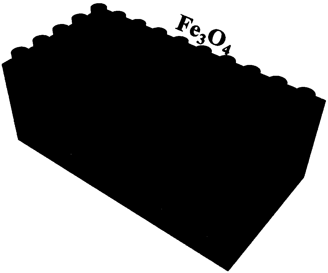
[0038] Place a mask plate on the upper surface of the BTO ferroelectric layer, with Fe 3 o 4 As the target material, the third deposition is carried out on the surface of the BTO ferroelectric layer with the mask plate placed by the pulsed laser deposition method to form Fe 3 o 4 Magnetic nanocolumn array, removing the mask plate to obtain a multiferroic heterojunction.

[0039] In the present invention, SRO is used as a target material, ...

Embodiment 1

[0049] (1) Place the STO substrate on the pedestal in the growth chamber of the pulsed laser deposition system, place the SRO target on the target position of the pulsed laser deposition system, and adjust the target position directly above the STO substrate, The distance between the STO substrate and the SRO target is 60cm; the cavity is closed, the temperature of the STO substrate is heated to 700°C, and the pulsed laser deposition method is adopted under the conditions of laser energy of 300mJ, frequency of 10Hz, and oxygen partial pressure of 100mTorr Growing an SRO bottom electrode layer on the upper surface of the STO substrate, to a thickness of 30nm to the SRO bottom electrode layer;

[0050] (2) At 750°C, the laser energy is 300mJ, the frequency is 10Hz, and the oxygen partial pressure is 5×10 -3 Under the condition of Torr, utilize BTO target material to grow tetragonal phase BTO ferroelectric layer on the upper surface of the SRO bottom electrode layer that describe...

Embodiment 2

[0053] The multiferroic heterojunction was prepared according to the method of Example 1, except that the temperature was lowered to 350°C in step (2), and Fe was grown at 350°C in step (3). 3 o 4 Magnetic nanopillar arrays.


PUM

PropertyMeasurementUnit
thicknessaaaaaaaaaa
thicknessaaaaaaaaaa
diameteraaaaaaaaaa

Abstract

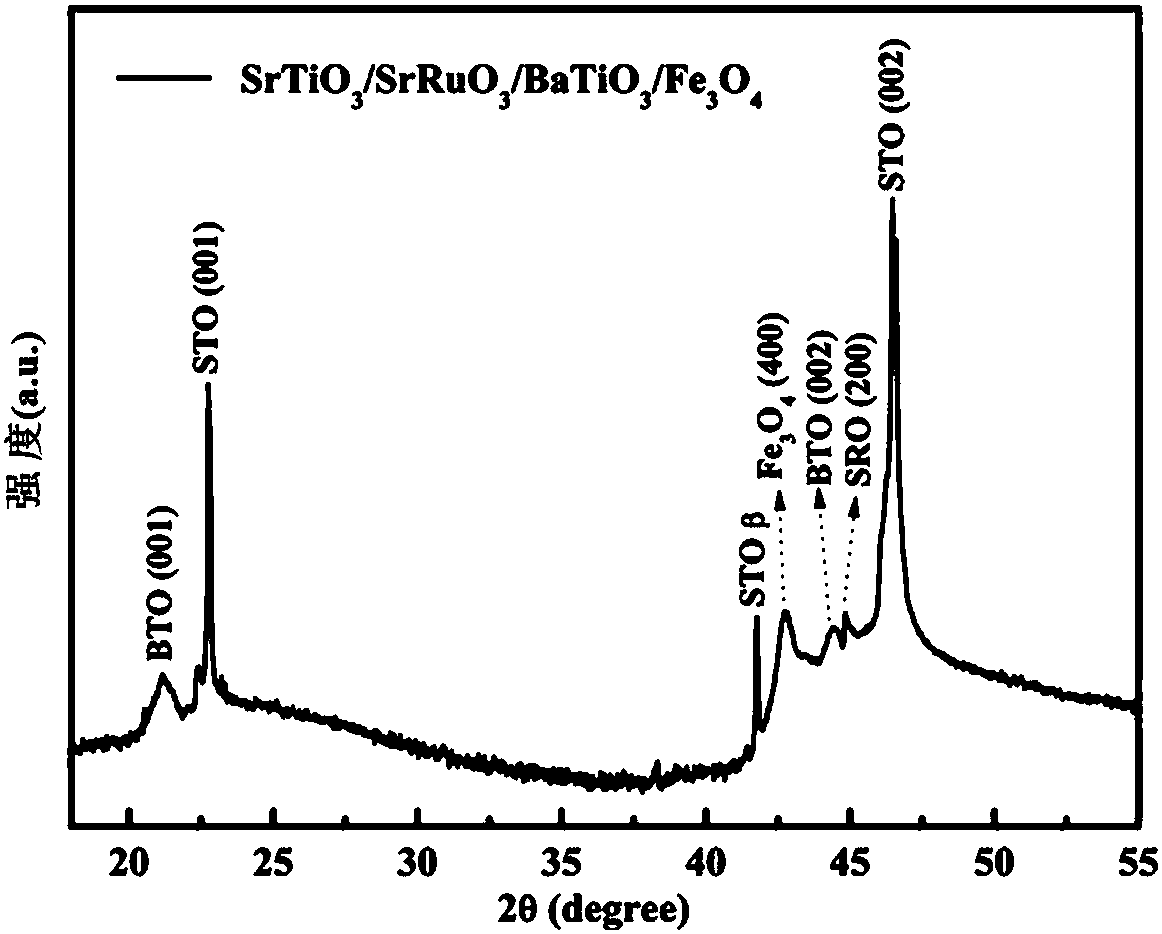
The invention provides a multiferroic heterojunction, sequentially comprising a strontium titanate substrate, a strontium ruthenate bottom electrode layer, a barium titanate ferroelectric layer and aferroferric oxide magnetic nano-column array from bottom to top. According to the scheme of the invention, barium titanate is used as the ferroelectric layer and ferroferric oxide is used as the magnetic nano-column array, so that the formed multiferroic heterojunction has excellent ferroelectric and ferromagnetic properties; ferroferric oxide can not only regulate and control the magnetic properties through ion movement, but also can be used as an electrode during flipping ferroelectric polarization; and the process of adopting an electric field to control the magnetization orientation at room temperature in a stable, reversible and nonvolatile mode can be achieved, and the scheme is beneficial to the development of memories and spin-electronic devices in the future, and lays a foundationfor realizing ultra-fast data storage and processing with high density and low power consumption.

Description

technical field [0001] The invention relates to the technical field of multiferroic composite thin films, in particular to a multiferroic heterojunction and a preparation method thereof. Background technique [0002] The biggest disadvantage of the currently widely used MRAM is that it requires a large current to write data, which consumes a lot of energy. However, the method of writing data directly using an external voltage and then reading data with a magnetic head can greatly reduce the energy consumption of writing, and realize non-contact and non-destructive readout. This storage method is called "electromagnetic readout". "storage. In order to realize "electrical writing and magnetic reading" storage, the most critical part is to realize the function of electric field flipping magnetic moment orientation in the material. However, the electronically controlled magnetic effect realized in single-phase multiferroic materials is limited by its antiferromagnetic order an...

Claims


Application Information

Patent Timeline
Patent Type & Authority Applications(China)
IPC IPC(8): H01L43/10H01L43/12H10N50/01
CPCH10N50/85H10N50/01
Inventor 钟高阔安峰李奥林谭锐谢淑红钟向丽王金斌
Owner XIANGTAN UNIV
Learn More