
River sludge treatment device

A treatment device and river sludge technology, applied in sludge treatment, water/sludge/sewage treatment, fixed/solidified sludge treatment, etc., can solve the problems of river sludge treatment work, high sludge clay content and long time consumption and other problems, to achieve the effect of increasing the consolidation effect, buffering the vibration frequency, and increasing the safety

Pending Publication Date: 2018-10-02
杨程飞扬
View PDF3 Cites 0 Cited by
  • Summary
  • Abstract
  • Description
  • Claims
  • Application Information

AI Technical Summary

Problems solved by technology

[0002] At present, most of the silt cleared from the river is in the storage yard. After the foundation treatment, the silt storage yard can be used for construction, landscape and farmland after the problem of its long-term swamp state is solved. This foundation treatment process is silt consolidation. During the drainage process, silt has high clay content, poor water permeability, and long consolidation time under the action of its own weight. How to better deal with river silt has a significant impact on river management and planning
[0003] However, the existing river silt treatment device has poor consolidation effect, consumes a lot of time, and cannot handle the river silt well.

Method used


Image

  • River sludge treatment device
  • River sludge treatment device
  • River sludge treatment device

Examples


Embodiment 1

[0022] A method for preparing an inorganic heat insulation board material, characterized in that the method comprises the following steps:

[0023] Step 1. At room temperature, place 1 part of polypropylene fiber in 25 parts of deionized water for ultrasonic dispersion, then add 80 parts of modified silicate ceramic composite cement powder and 8 parts of water glass, and stir to obtain a mixed solution;

[0024] Step 2, adding 2 parts of hexamethylphosphoric triamide, 1 part of azodicarbonamide, and 1 part of ethylenediamine tetramethylene phosphonic acid to the above mixed solution and stirring evenly to obtain a geopolymer slurry;

[0025] Step 3, adding 5 parts of hydrogen peroxide, 0.5 parts of foaming catalyst sodium chlorate and 0.5 parts of foam stabilizer hexaglycerol monostearate into the geopolymer slurry, stirring for 3 minutes to obtain a foaming slurry;

[0026] Step 4, Stir the above-mentioned foaming slurry and put the mixture into the mold, add glass fiber mesh...

Embodiment 2

[0035] Step 1. At room temperature, place 1 part of polypropylene fiber in 25 parts of deionized water for ultrasonic dispersion, then add 70 parts of modified silicate ceramic composite cement powder and 8 parts of water glass, and stir evenly to obtain a mixed solution; the rest are prepared Same as Example 1.

Embodiment 3

[0037] Step 1. At room temperature, place 1 part of polypropylene fiber in 25 parts of deionized water for ultrasonic dispersion, then add 60 parts of modified silicate ceramic composite cement powder and 8 parts of water glass, and stir evenly to obtain a mixed solution; the rest are prepared Same as Example 1.


PUM


Abstract

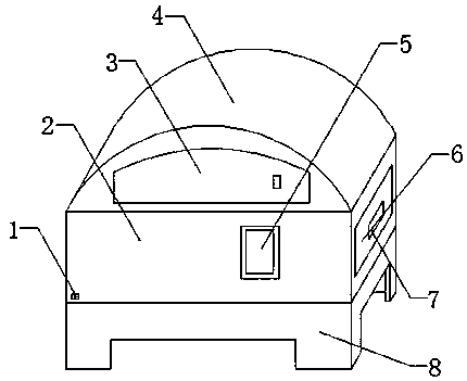
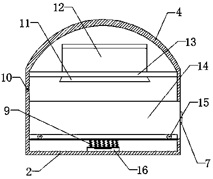
The invention discloses a river sludge treatment device which comprises a working box. A supporting base is fixedly connected at the bottom end of the working box, a machine top box is fixedly connected at the upper end of the working box, a control panel is fixedly connected on the front surface of the working box, a power socket is fixedly connected on the left lower portion of the control panel, a maintenance door is movably connected on the front surface of the machine top box, a warm air machine is fixedly connected in the machine top box, an air outlet pipe is fixedly connected at the lower end of the warm air machine, a sludge storage box is movably connected on the lower portion of the air outlet pipe, the device is provided with an oscillation machine, so that sludge storage box can be oscillated through a spring, curing efficiency can be effectively increased, curing degree of sludge is higher, the warm air machine can effectively provide necessity energy for curing of the sludge, curing speed is higher, and the oscillation frequency of the oscillation machine can be effectively buffered by the spring, so that the oscillation frequency is reasonable and effective. The device is simple in structure and convenient to use.

Description

technical field [0001] The invention relates to the technical field of river course management, in particular to a river course silt treatment device. Background technique [0002] At present, most of the silt cleared from the river is in the storage yard. After the foundation treatment, the silt storage yard can be used for construction, landscape and farmland after the problem of its long-term swamp state is solved. This foundation treatment process is silt consolidation. In the process of drainage, silt has high clay content, poor water permeability, and long consolidation time under the action of self-weight. How to better deal with river silt has a major impact on river management and planning. [0003] However, the existing river silt treatment device has poor consolidation effect, consumes a lot of time, and cannot handle the river silt well. Contents of the invention [0004] The object of the present invention is to provide a river channel sludge treatment device...

Claims


Application Information

Patent Timeline
IPC IPC(8): C02F11/00C02F11/12C04B28/04C04B111/40
CPCC02F11/008C02F11/12C04B28/04C04B2111/00629C04B2111/40C04B2201/32C04B22/00C04B24/003C04B24/129C04B22/068C04B22/124C04B24/045C04B38/10C04B18/023C04B14/102C04B18/0445C04B16/0633C04B14/366
Inventor 马海龙王威
Owner 杨程飞扬
Learn More