Angular velocity measuring apparatus and method based on broadband tunable photoelectric oscillator

A photoelectric oscillator and measuring device technology, applied in the field of angular velocity measurement and microwave photonics, can solve the problems of limited sensitivity improvement, high measurement sensitivity, complex system, etc., and achieve the effects of improving measurement sensitivity, increasing range, and low cost

Active Publication Date: 2018-10-02
BEIJING JIAOTONG UNIV
View PDF8 Cites 6 Cited by
  • Summary
  • Abstract
  • Description
  • Claims
  • Application Information

AI Technical Summary

Problems solved by technology

However, with these schemes, the degree of sensitivity improvement is limited, or the system becomes more complicated, which is difficult to apply in practice
[0005] In the prior art, the resonance-based optical fiber structure has become a research hotspot. Like the angular velocity measurement scheme based on the ring laser cavity, it uses the frequency difference to measure the angular velocity, so the measurement sensitivity is high, and the scheme uses a fiber optic loop. No precise manufacturing process is required, but the measurement performance of this scheme is related to the quality factor (Q value) of the resonant cavity, and complex demodulation and feedback structures are required to obtain angular velocity, so in order to realize practicality, there are still many problems to be solved. solve

Method used


Image

  • Angular velocity measuring apparatus and method based on broadband tunable photoelectric oscillator
  • Angular velocity measuring apparatus and method based on broadband tunable photoelectric oscillator
  • Angular velocity measuring apparatus and method based on broadband tunable photoelectric oscillator

Examples


Embodiment 1

[0067] Embodiments of the present invention provide an angular velocity measurement device and method based on a broadband tunable optoelectronic oscillator, which maps the angular velocity to the frequency of the microwave signal generated by the optoelectronic oscillator, increasing the angular velocity measurement sensitivity and dynamic range.

[0068] An aspect of the embodiments of the present invention provides an angular velocity measurement device based on a broadband tunable photoelectric oscillator.

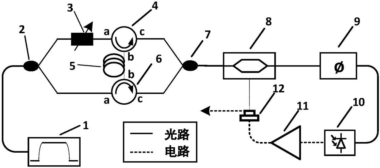
[0069] Schematic structure of an angular velocity measurement device based on a broadband tunable photoelectric oscillator provided by an embodiment of the present invention Figure 1 Such as figure 1 As shown, the device includes: a light source 1, a first optical coupler 2, a second optical coupler 7, an adjustable optical delay line 3, a first optical circulator 4, a second optical circulator 6, a Sagnac ring 5, an optical Modulator 8 , dispersive element 9 , photo...

Embodiment 2

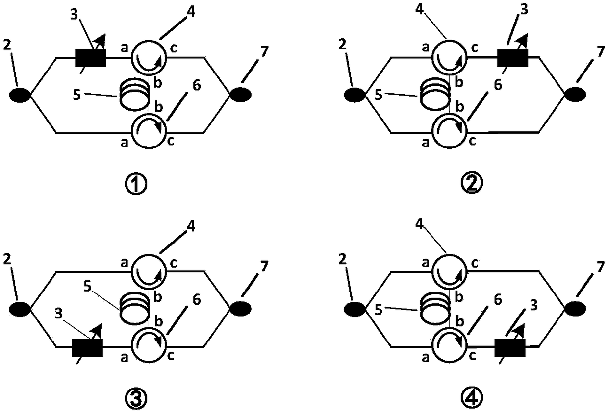
[0123] This embodiment provides an angular velocity measurement device based on a broadband tunable photoelectric oscillator, and its specific implementation structure is as follows Figure 4 As shown, the measurement device includes: a light source 1, a first optical coupler 2, a second optical coupler 7, an adjustable optical delay line 3, a first optical circulator 4, a second optical circulator 6, a Sagnac ring 5, Optical modulator 8 , dispersion element 9 , photodetector 10 , microwave amplifier 11 and power divider 12 .

[0124] The specific principle and implementation manner of using the device of the embodiment of the present invention to measure the angular velocity based on the broadband tunable optoelectronic oscillator are similar to the description in the first embodiment above, and will not be repeated here. The difference between the embodiment of the present invention and the first embodiment is that: in the embodiment of the present invention, the optical sig...

Embodiment 3

[0126] This embodiment provides an angular velocity measurement device based on a broadband tunable photoelectric oscillator, and its specific implementation structure can be as follows Figure 5 As shown, the measurement device includes: a light source 1, a first optical coupler 2, a second optical coupler 7, an adjustable optical delay line 3, a first optical circulator 4, a second optical circulator 6, a Sagnac ring 5, Optical modulator 8 , dispersion element 9 , photodetector 10 , microwave amplifier 11 and power divider 12 .

[0127] The specific principle and implementation manner of using the device of the embodiment of the present invention to measure the angular velocity based on the broadband tunable optoelectronic oscillator are similar to the description in the first embodiment above, and will not be repeated here. The difference between the embodiment of the present invention and the first embodiment is that: in the embodiment of the present invention, the optical...


PUM


Abstract

The invention provides an angular velocity measuring apparatus and method based on a broadband tunable photoelectric oscillator. The device comprises a light source, a first optical coupler, an adjustable light delay line, a first optical circulator, a second optical circulator, a Sagnac ring, a second optical coupler, a light modulator, a dispersive element, a photoelectric detector, a microwaveamplifier and a power divider. According to the invention, the Sagnac ring is connected between two arms of a mach zehnder interferometer (MZI) by the first optical circulator and the second optical circulator and thus a phase change caused by a Sagnac effect is transformed into a free spectral range (FSR) change of interference signal outputting by the MZI, so that mapping of a frequency change of the microwave signal generated by the photoelectric oscillator is realized. Therefore, the angular velocity of Sagnac ring rotation is obtained by monitoring the frequency change of the output microwave signal of the photoelectric oscillator. With the microwave photon filtering technology, the measurement sensitivity is enhanced and the angular velocity measurement range is extended. Moreover, the ngular velocity measuring apparatus has advantages of simple structure and low cost.

Description

technical field [0001] The invention relates to the field of angular velocity measurement and microwave photon technology, in particular to an angular velocity measurement device and method based on a broadband tunable photoelectric oscillator. Background technique [0002] As an important part of the inertial system, the angular velocity measurement technology has a wide range of applications in the fields of military, navigation, aviation, communication, industry and civil navigation. The angular velocity measurement scheme based on optical technology has been widely concerned and researched by relevant scholars at home and abroad because of its advantages such as high measurement accuracy, light weight, and large dynamic range. The basic principle is based on the Sagnac effect [E J Post.Sagnac effect.Reviews of Modern Physics, 1967, 39(2):475-493.], that is, the two beams of light traveling along the forward and reverse directions in the optical ring rotate in the optical...

Claims


Application Information

Patent Timeline
Patent Type & Authority Applications(China)
IPC IPC(8): G01P3/36
Inventor 王目光张静唐宇丁琪牟宏谦武蓓蕾
Owner BEIJING JIAOTONG UNIV
Why Eureka
Try Eureka