
Method and application for solid-liquid separation treatment of waste drilling fluid

A waste drilling fluid, solid-liquid separation technology, applied in the direction of centrifugal separation water/sewage treatment, mining wastewater treatment, mechanical oscillation water/sewage treatment, etc., can solve the problems of promotion and application limitations, high cost, and environmental hazards, etc. Achieve the effects of strong operability, simple treatment process and low treatment cost

Inactive Publication Date: 2018-10-12
CHINA PETROCHEMICAL CORP +3
View PDF9 Cites 5 Cited by
  • Summary
  • Abstract
  • Description
  • Claims
  • Application Information

AI Technical Summary

Problems solved by technology

To a certain extent, this device has realized the resourceful and harmless treatment of waste mud and cuttings in deep well sulfur-polysulfurized drilling fluid, and recycled and utilized barite in part of the drilling fluid. However, the composition of the treatment device is complicated and the treatment process is complicated. high cost
[0007] The above-mentioned waste drilling fluid treatment methods have their own limitations, such as complex solid-liquid separation process, high cost, environmental hazards, and difficulty in harmless treatment or resource utilization. Their promotion and application have been restricted. limit
In addition, the value components in the waste drilling fluid after the solid-liquid separation treatment have not been utilized as resources or only partially utilized, and the harmless treatment and resource utilization of the waste drilling fluid have not been realized to the greatest extent. It is difficult to meet the needs of the oil drilling industry. clean production requirements

Method used


Image

  • Method and application for solid-liquid separation treatment of waste drilling fluid
  • Method and application for solid-liquid separation treatment of waste drilling fluid
  • Method and application for solid-liquid separation treatment of waste drilling fluid

Examples


Embodiment 1

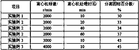
[0026] Example 1: When the waste polysulfide drilling fluid is not subjected to ultrasonic treatment, the percentage of solid phase content that can be separated by centrifuge treatment, a certain amount of waste polysulfide drilling fluid is put in the centrifuge, and the centrifuge speed is 2000 r / min, The centrifugation time was 10 min, and the mass of the solid phase of the centrifuged sample was measured by an electronic balance, and the percentage of the mass of the separated solid phase to the mass of the sample was calculated, and the percentage of the separated solid phase was 30%, as shown in Table 1.

Embodiment 2

[0027] Example 2: Without ultrasonic treatment, the percentage of solid phase content that can be separated from waste polysulfide drilling fluid after centrifuge treatment under different centrifuge centrifugation time, according to the method of centrifuge treatment Example 1, the difference is that, respectively, use 20 min, 40 min, 60 min instead of 10 min, so as to obtain the percentage of the solid phase mass separated from the waste polysulfide drilling fluid in different centrifugation times to the sample mass, take a certain amount of waste polysulfide drilling fluid in the centrifuge, and The speed of the centrifuge is 2000 r / min, the centrifugation time is 20 min, the percentage of the separated solid phase is 33%, the speed of the centrifuge is 2000 r / min, the centrifugation time is 40 min, the percentage of the separated solid phase is 34%, and the speed of the centrifuge is 2000 r / min, the centrifugation time is 60 min, and the percentage of separated solid phase...

Embodiment 3

[0028] Example 3: Without ultrasonic treatment, the percentage of solid phase content that can be separated from the waste polysulfide drilling fluid at different centrifuge centrifugal speeds after centrifuge treatment, according to the method of centrifuge treatment Example 1, the difference is that, respectively, use 20 min, 40 min, 60 min instead of 10 min, so as to obtain the percentage of the solid phase mass separated from the waste polysulfide drilling fluid in different centrifugation times to the sample mass, take a certain amount of waste polysulfide drilling fluid in the centrifuge, and The speed of the centrifuge is 3000 r / min, the centrifugation time is 10 min, and the percentage of the separated solid phase is 43%. The speed of the centrifuge is 4000 r / min, the centrifugation time is 10 min, and the percentage of the separated solid phase is 45%, as shown in Table 1.

[0029] Table 1 Comparison of treatment effects of waste sulfide drilling fluid with different c...


PUM


Abstract

The invention relates to a method and an application for solid-liquid separation treatment of a waste drilling fluid. The technical scheme comprises three steps of ultrasonic wave treatment, centrifugation of a waste drilling fluid, and separation of solid phase and liquid phase. The ultrasonic treatment time is 15-60 min, the ultrasonic wave treatment frequency is 18-25 kHz, the centrifugation time of a centrifugal machine is 10-60 min, and the centrifugation rotation speed of the centrifugal machine is 2000-4000 r / min. The separation method of the solid phase and liquid phase of the waste drilling fluid is to separate the waste drilling fluid subjected to the centrifugation by the centrifugal machine. The beneficial effects of the method is as the follows that compared with conventionalwaste-drilling-fluid solid-liquid separation methods, such as plate-frame pressure filtration, high-speed centrifugation and the like, the solid-liquid separation method of the waste drilling fluid provided by the invention is carried out by using the ultrasonic wave treatment, the centrifugation of the waste drilling fluid, and the separation of the solid phase and liquid phase; the treatment technology is simple, the operability is high, and the treatment cost is low. The method is especially suitable for harmless treatment and resource utilization of waste drilling fluids in the explorationand development process of petroleum and natural gas.

Description

technical field [0001] The invention relates to a solid-liquid separation treatment method for drilling fluid, in particular to a solid-liquid separation treatment method for waste drilling fluid and its application. Background technique [0002] Drilling fluid is the "blood" of drilling engineering. Its main functions include cleaning the bottom of the well, carrying cuttings, cooling and lubricating the drill string, balancing formation pressure, maintaining the stability of the well wall, suspending cuttings and weighting agents, effectively transmitting hydraulic power, Bear part of the gravity of the drill pipe casing, provide drilled formation data, and hydraulically assist rock breaking, etc. However, with the continuous improvement of my country's environmental protection laws and regulations and the continuous improvement of environmental protection requirements, waste drilling fluid has become one of the main pollution sources of drilling engineering. Taking the cu...

Claims


Application Information

Patent Timeline
Patent Type & Authority Applications(China)
IPC IPC(8): C02F1/36C02F1/38C02F103/10
CPCC02F1/36C02F1/38C02F2103/10
Inventor 陈二丁刘均一王成文张桂林邱维清张景红张海青魏晓彤于倩赵红香
Owner CHINA PETROCHEMICAL CORP
Learn More