


Quick Research
Generate reliable direction feasibility study reports for your R&D in just a few steps.

Technical Q&A
Discover and master advanced knowledge NOW. Basics, ideas, possibilities, all at once.

Find Solutions
As an expert in R&D theories, this can generate solutions to your technical problems instantly.

Evaluate Feasibility
Analyze your overall solution with one click, know your potential R&D risks in advance.

Monitor Landscape
Get weekly tech updates, stay abreast of the latest tech innovations and key insights.
Microfluidic paper chip for chemiluminescence time resolution and detection as well as preparation method and application thereof
A microfluidic paper chip, chemiluminescence technology, applied in chemiluminescence/bioluminescence, analysis by chemical reaction of materials, etc., can solve the problems of limited use range, solution migration, troublesome operation, etc., to overcome the problem of sample solution and the effect of the influence of the chemiluminescence reaction signal
- Summary
- Abstract
- Description
- Claims
- Application Information
AI Technical Summary
Problems solved by technology
Method used
Image

Examples
Embodiment 1
[0040] The specific production, assembly and testing process is as follows:
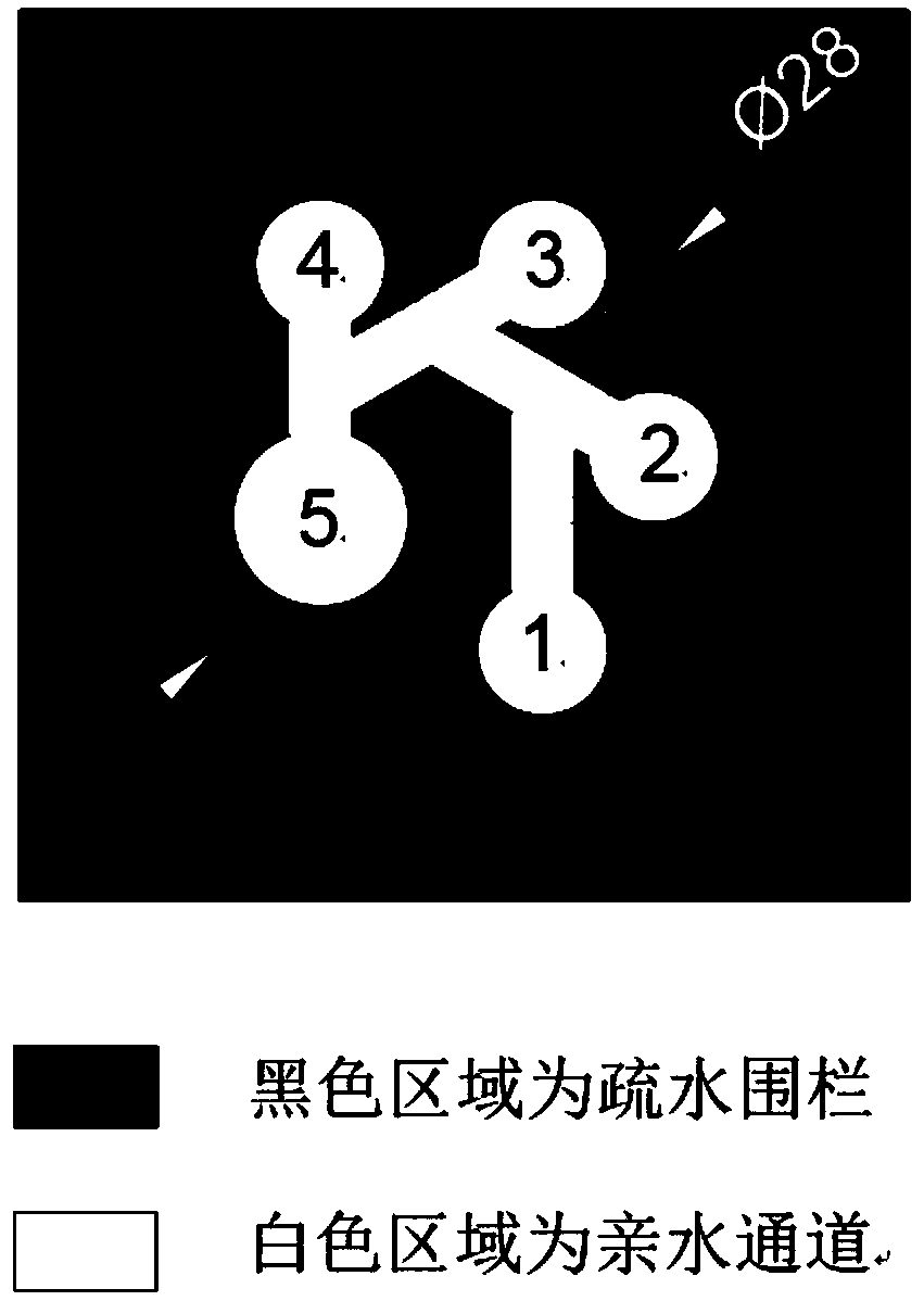
[0041] 1) First use Computer Aided Design (CAD) drawing software to design the pattern of the chemiluminescent time-resolved detection microfluidic paper chip (see attached figure 1 shown). The design parameters of the paper chip are as follows:
[0042] The circular sampling hole is connected to the first-level flow channel, part of the first-level flow channel is branched out from the second-level flow channel, and the second-level flow channel is deflected 60° in one direction to branch out into the third-level flow channel, and the third-level flow channel is deflected in the same direction 60° bifurcates into four-stage circulation channels. One end of each secondary circulation channel is connected to the middle part of the upper-level circulation channel, and the other end is connected to a circular detection hole.
[0043] The diameter of the above-mentioned circular sampling hole is 8 mm,...
Embodiment 2
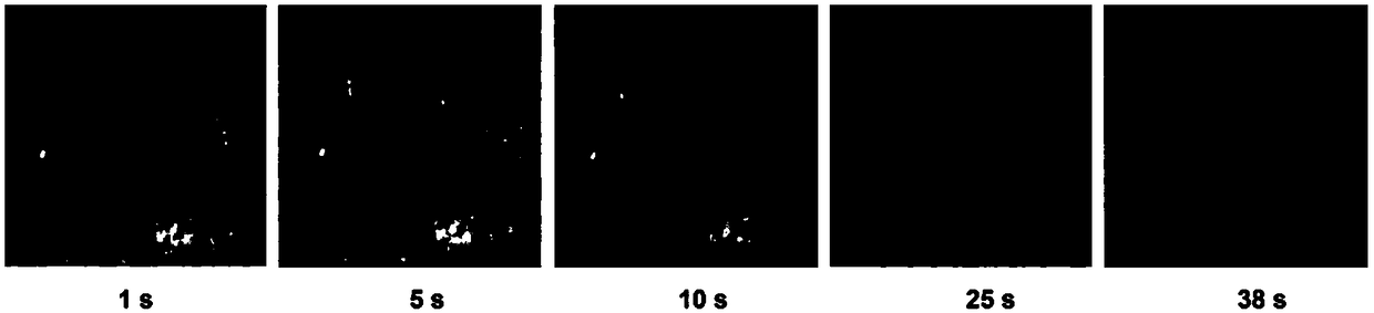
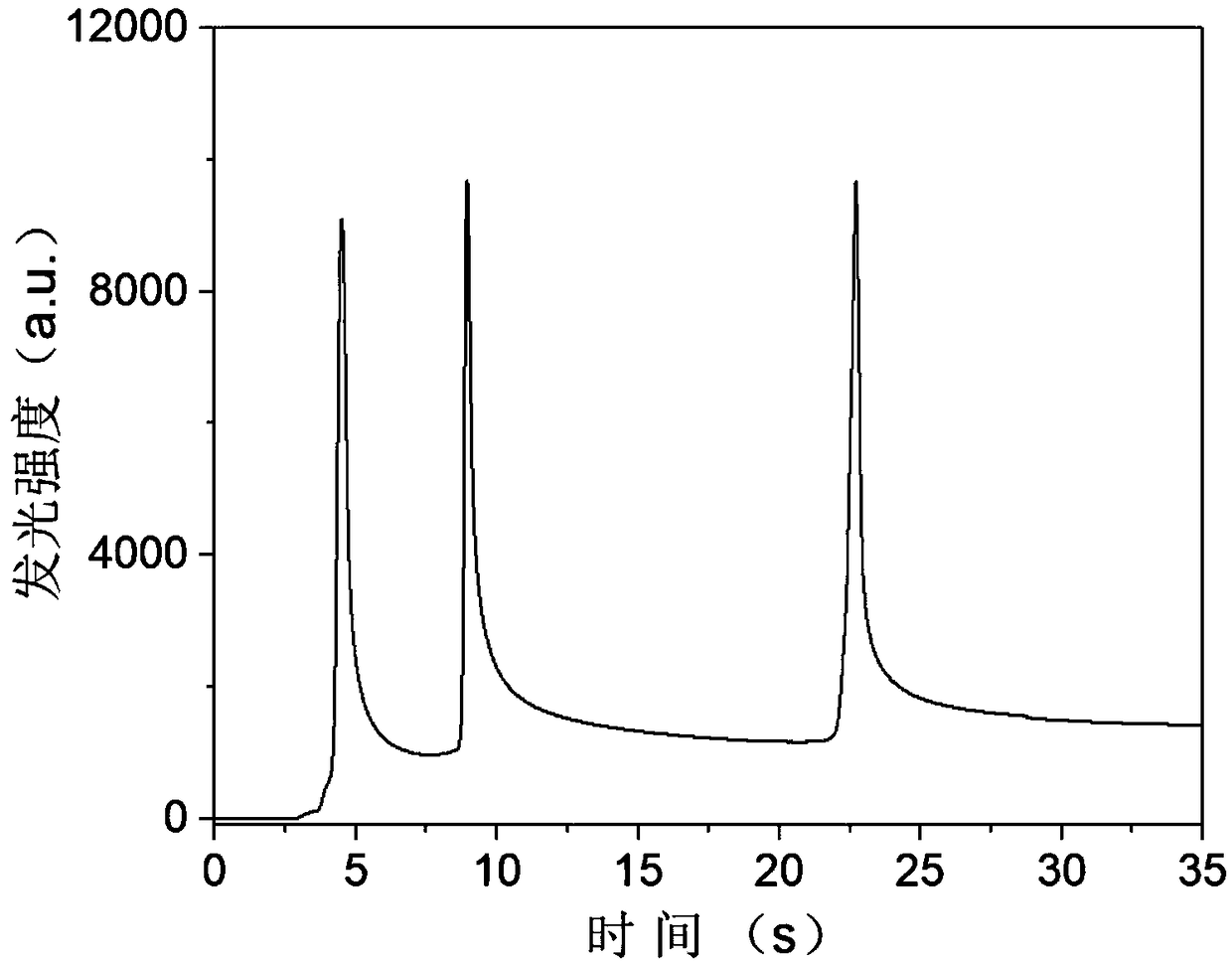
[0049] In order to prove that the microfluidic paper chip of the present invention can realize the time-resolved detection of chemiluminescent signals, the inventors assembled a chemiluminescent functionalized microfluidic paper chip and used a chemiluminescent instrument to detect hydrogen peroxide. The specific method is as follows:
[0050] 1) First, use Photoshop CS4 software to design the pattern of the microfluidic paper chip for chemiluminescence time-resolved detection. The design parameters of the paper chip are as follows:
[0051] The circular sampling hole is connected to the first-level flow channel, part of the first-level flow channel branches out to the second-level flow channel, and the second-level flow channel is deflected by 60° in one direction to branch out to the third-level flow channel. One end of each secondary circulation channel is connected to the middle part of the upper-level circulation channel, and the other end is connected to a circular dete...
Embodiment 3
[0057] In order to prove the beneficial effect of the present invention, the inventor used the paper chip of Example 2 to prepare a chemiluminescent microfluidic paper chip for the simultaneous detection of glucose, uric acid and cholesterol. The specific method is as follows:
[0058] 1) First, prepare a microfluidic paper chip as described in step 1) of Example 2. In this embodiment, the total number of circulation channels of the microfluidic paper chip is three, and the number of detection holes is three.
[0059] 2) Chitosan was dissolved in 0.25% (v / v) glacial acetic acid, and a chitosan solution of 1 mg / mL was prepared, and 3.0 μL of the above-mentioned 1 mg / mL chitosan solution was added dropwise to the paper chip. In the three detection wells, dry at room temperature for 3 minutes.
[0060] 3) Add 3.0μL 50U / mL glucose oxidase and 0.15mg / mL horseradish peroxidase mixture to the glucose detection area labeled 1 on the paper chip; add 3.0μL 50U / mL urate oxidase and 0.15...
PUM
 Abstract
Description
Claims
Application Information
 - R&D Engineer
- R&D Manager
- IP Professional
- Industry Leading Data Capabilities
- Powerful AI technology
- Patent DNA Extraction
Browse by: Latest US Patents, China's latest patents, Technical Efficacy Thesaurus, Application Domain, Technology Topic, Popular Technical Reports.
© 2024 PatSnap. All rights reserved.Legal|Privacy policy|Modern Slavery Act Transparency Statement|Sitemap|About US| Contact US: help@patsnap.com