3D printing device and printing method based on electrostatic spinning principle

A 3D printing and electrospinning technology, applied in the field of 3D printing, can solve the problem of not having 3D printing technology combined with electrospinning technology, etc., to achieve the effect of delicate appearance, high bonding force, and widening the range of choices.

Inactive Publication Date: 2018-10-23
JIANGNAN UNIV
View PDF3 Cites 8 Cited by
  • Summary
  • Abstract
  • Description
  • Claims
  • Application Information

AI Technical Summary

Problems solved by technology

At present, there are almost no patents combining 3D printing technology with electrospinning technology

Method used


Image

  • 3D printing device and printing method based on electrostatic spinning principle
  • 3D printing device and printing method based on electrostatic spinning principle
  • 3D printing device and printing method based on electrostatic spinning principle

Examples


example 1

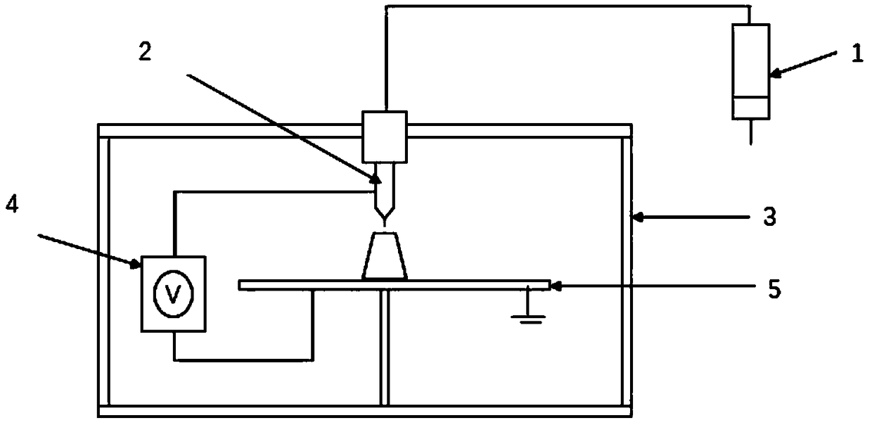
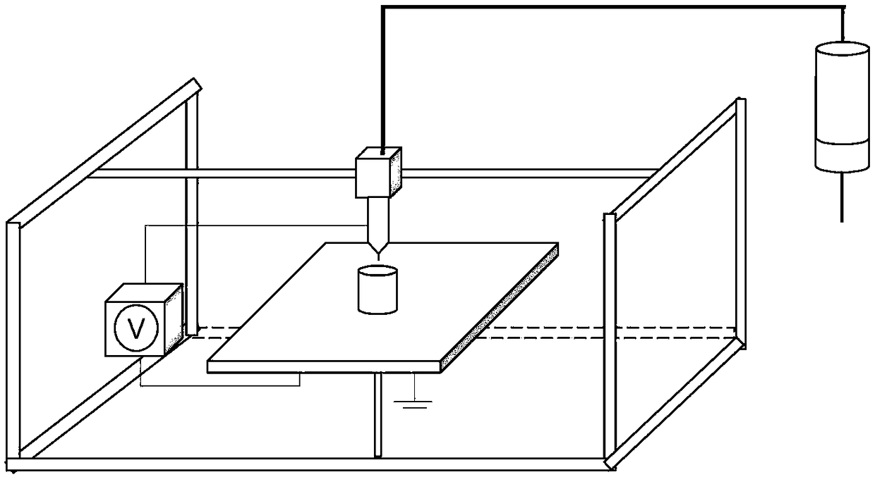
[0050] A 3D printing device based on the principle of electrospinning, the basic structure of which includes a micro-injection pump 1 . The injection outlet of the micro injection pump 1 is connected to the material receiving port of the print head 2 . The printing nozzle 2 is fixed on the three-dimensional space moving frame 3 . It also includes a receiving platform 5 located under the print head 2 . A high voltage power supply 4 is also included. The anode of the high-voltage power supply 4 is connected to the print head 2 . The negative pole of the high voltage power supply 4 is connected on the receiving platform 5 . The plane of the receiving platform 5 is divided into a plurality of grid units 10 . A voltage control device is installed below the receiving platform 5 to control the voltage of each grid unit 10 .

[0051] Receiving the voltage control device under Ping An 5, specifically the integrated circuit laid on the back of the receiving platform 5, divides the ...

Embodiment 2

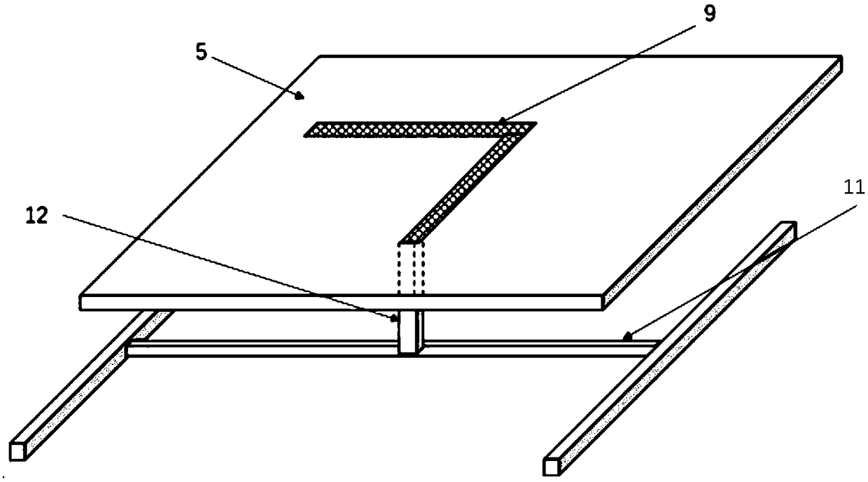
[0053] The basic structure of embodiment 2 is the same as that of embodiment 1, but the voltage control device below the receiving platform 5 is different, specifically, including the terminal control frame 11 installed below the receiving platform 5; There is a voltage control terminal 12; the terminal control frame 11 controls the voltage control terminal 12 to move in a plane parallel to the receiving platform 5; The voltage range of the voltage control terminal 12 is 0-15kv, and the receiving platform 5 is made of conductive metal. The moving path and moving speed of the voltage controlling terminal 12 are completely synchronized with the moving path and moving speed of the printing nozzle 2 .

Embodiment 3

[0055] The basic structure of embodiment 3 is the same as embodiment 1.

[0056] Specifically, a high polymer for printing dissolved in a volatile solvent is placed in the micro-injection pump 1, and the printing material is extruded through the micro-injection pump 1 at a room temperature of 20°C and a relative humidity of 25%. 1 is connected with the printing nozzle 2 by a hose, and the polymer forms a fine jet at the tip of the printing nozzle 2 under the action of the high-voltage electrostatic field generated by the high-voltage power supply 4, and the three-dimensional space moving frame 3, that is, the three-dimensional gantry frame controls the printing nozzle 2 Mobile printing, at the same time, the micro-cooling and hot air control device 8 outputs hot air to accelerate the volatilization of the solvent, so that the material is solidified. After the cross-section of one layer is printed, the receiving platform 5 is lowered to the height of one layer and printed again....


PUM

PropertyMeasurementUnit
porosityaaaaaaaaaa

Abstract

The invention discloses a 3D printing device and a printing method based on electrostatic spinning principle. The device comprises a micro-injection pump, a receiving platform and a high-voltage powersupply, wherein an injection outlet of the micro-injection pump is connected to a raw material receiving opening of a printing nozzle; the printing nozzle is fixed on a three-dimensional space movement frame; the receiving platform is located under the printing nozzle; a positive pole of the high-voltage power supply is connected to the printing nozzle; a negative pole of the high-voltage power supply is connected to the receiving platform; the plane of the receiving platform is divided into multiple grid units; a voltage control device is mounted under the receiving platform and is used forcontrolling the voltage of each grid unit. The invention firstly proposes the idea of combining an electrostatic spinning technology with a 3D printing technology, so that the 3D printing device withmore complete functions is achieved.

Description

technical field [0001] The invention relates to 3D printing technology, in particular to a 3D printing device and printing method based on the principle of electrospinning. Background technique [0002] Fused deposition manufacturing technology (FDM) is to heat and extrude low-melting point filamentous materials through a hot-melt nozzle, and at the same time, the three-dimensional nozzle deposits at the designated position according to the path controlled by the CAD layered data. After rapid cooling, a layer of cross-section is formed, and the platform drops to a height. Print the next layer, deposit it layer by layer repeatedly, and form the entire solid prototype after solidification. [0003] The materials formed by the FDM process are mainly thermoplastic materials such as nylon, ABS plastic, and PLA plastic. [0004] At present, the common FDM nozzle is 0.4mm, and the filament material used at the same time is 1.75mm. However, due to the solidification deposition betw...

Claims


Application Information

Patent Timeline
Patent Type & Authority Applications(China)
IPC IPC(8): B29C64/118B29C64/393B33Y30/00B33Y50/02
CPCB29C64/118B29C64/393B33Y30/00B33Y50/02
Inventor 肖学良刘良强钱坤卢雪峰
Owner JIANGNAN UNIV
Why Eureka
Try Eureka