
Distributed optical fiber temperature measurement system

A technology of distributed optical fiber and sensing optical fiber, applied in thermometers, measuring devices, measuring heat, etc., can solve the problems of deteriorating real-time performance and increasing temperature measurement time, and achieve simple structure, increased sampling rate, and reduced spatial resolution Effect

Pending Publication Date: 2018-10-23
SHANGHAI GUANGWEI ELECTRIC POWER TECH CO LTD
View PDF0 Cites 3 Cited by
  • Summary
  • Abstract
  • Description
  • Claims
  • Application Information

AI Technical Summary

Problems solved by technology

The improvement of spatial resolution is limited by the pulse width of the laser and the sampling rate of the acquisition card. To ensure a spatial resolution of 1 meter, it is necessary to ensure that the pulse width of the laser is less than 10 ns and the sampling rate of the acquisition card is greater than 100 Mb / s. The common method to improve temperature accuracy is the digital cumulative average method, which can improve the signal-to-noise ratio to a certain extent, but increases the temperature measurement time, and often deteriorates its real-time performance in order to achieve sufficient accuracy.

Method used


Image

  • Distributed optical fiber temperature measurement system
  • Distributed optical fiber temperature measurement system
  • Distributed optical fiber temperature measurement system

Examples


Embodiment Construction

[0029] In order to make the technical problems, technical solutions and advantages to be solved by the present invention clearer, a detailed description will be given below in conjunction with the accompanying drawings and specific embodiments.

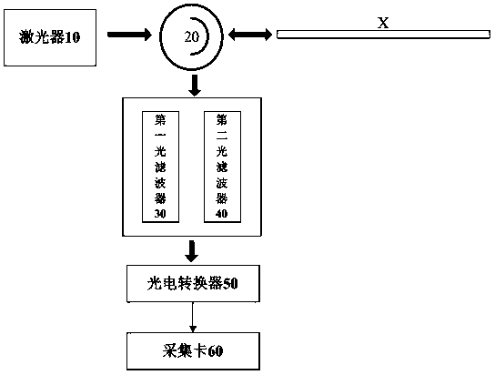
[0030] The sensing principle of the distributed optical fiber temperature measurement system is mainly based on the optical time domain reflection (O principle) of the optical fiber and the temperature effect of the optical fiber's back Raman scattering.

[0031] Principle of optical time domain reflection: When laser pulses are transmitted in an optical fiber, scattering occurs due to the microscopic non-uniformity of refractive index in the optical fiber. In the time domain, the time required for the incident light to return to the incident end of the fiber by backscattering is t, and the distance traveled by the laser pulse in the fiber is 2L, where v is the propagation speed of the light in the fiber, and C is the vacuum The speed of l...


PUM


Abstract

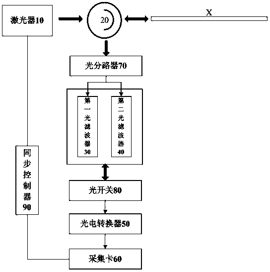
The invention discloses a distributed optical fiber temperature measurement system, which belongs to the technical field of optical fiber temperature measurement. The distributed optical fiber temperature measurement system comprises a laser, an optical circulator, a first optical filter, a second optical filter, a photoelectric conversion circuit and an acquisition card, wherein laser emitted bythe laser enters a to-be-detected sensing optical fiber through the optical circulator; backscattered light generated during the process during which the laser is propagated in the to-be-detected sensing optical fiber is returned to the optical circulator and then enters the first optical filter and the second optical filter for filtering; the filtered backscattered light enters the photoelectricconversion circuit; and electric signals outputted by the photoelectric conversion circuit are acquired by the acquisition card and are then transmitted to a computer to be processed to temperature signals. According to the distributed optical fiber temperature measurement system disclosed in the invention, the temperature precision of the distributed optical fiber temperature measurement system can be improved effectively, the stability is enhanced, and the spatial resolution is low.

Description

Technical field [0001] The invention relates to a distributed optical fiber temperature measurement system, belonging to the technical field of optical fiber temperature measurement. Background technique [0002] After more than ten years of development, the distributed optical fiber temperature measuring device has long measuring distance, high precision, [0003] It has the advantages of no measurement blind zone and strong anti-electromagnetic interference ability. It is widely used in power cable tunnels, integrated pipe corridors, coal industry and data centers and other fields that require temperature measurement, fire alarm, energy saving and emission reduction. [0004] The distributed optical fiber temperature measuring device is made by using the spontaneous Raman scattering effect. The anti-stokes signal is sensitive to temperature, and the Stokes signal is not sensitive to temperature. It can be calculated by the ratio of light intensity The temperature value of each poi...

Claims


Application Information

Patent Timeline
Patent Type & Authority Applications(China)
IPC IPC(8): G01K11/32
CPCG01K11/32G01K11/324
Inventor 陈博孙静姜涛
Owner SHANGHAI GUANGWEI ELECTRIC POWER TECH CO LTD
Learn More