A kind of anode steel claw guide rod group

A technology of anode steel claw and guide rod, which is applied to the field of anode steel claw guide rod group, can solve the problems of large consumption of aluminum/steel explosive welding block, small size of aluminum/steel explosive welding block, short service life, etc. Conducive to environmental protection, reduced material costs, and low manufacturing costs

Active Publication Date: 2020-06-05
重庆角鹿机械制造有限公司 +1
View PDF1 Cites 0 Cited by
  • Summary
  • Abstract
  • Description
  • Claims
  • Application Information

AI Technical Summary

Problems solved by technology

The traditional anode guide rod set has many disadvantages, one is that the size of the aluminum / steel explosion welding block is small, resulting in a high voltage drop, and due to the inconsistency of the thermal expansion coefficient of the aluminum / steel, the thermal expansion of the steel beam causes the anode steel claws to deform inwardly Or pull off the anode carbon block, which will affect the normal and stable production of the electrolytic cell; the second is that the connection between the bus bar and the anode steel claw guide rod is prone to arcing, and the service life is short; the third is that the contact resistance is large, the power loss is large, and the material consumption Large and costly; Fourth, the existing aluminum electrolysis production enterprises all need to use aluminum / steel explosion welding nuggets, which consume a large amount of aluminum / steel explosion welding nuggets and are likely to pollute the environment after being scrapped

Method used


Image

  • A kind of anode steel claw guide rod group
  • A kind of anode steel claw guide rod group
  • A kind of anode steel claw guide rod group

Examples


Embodiment 1

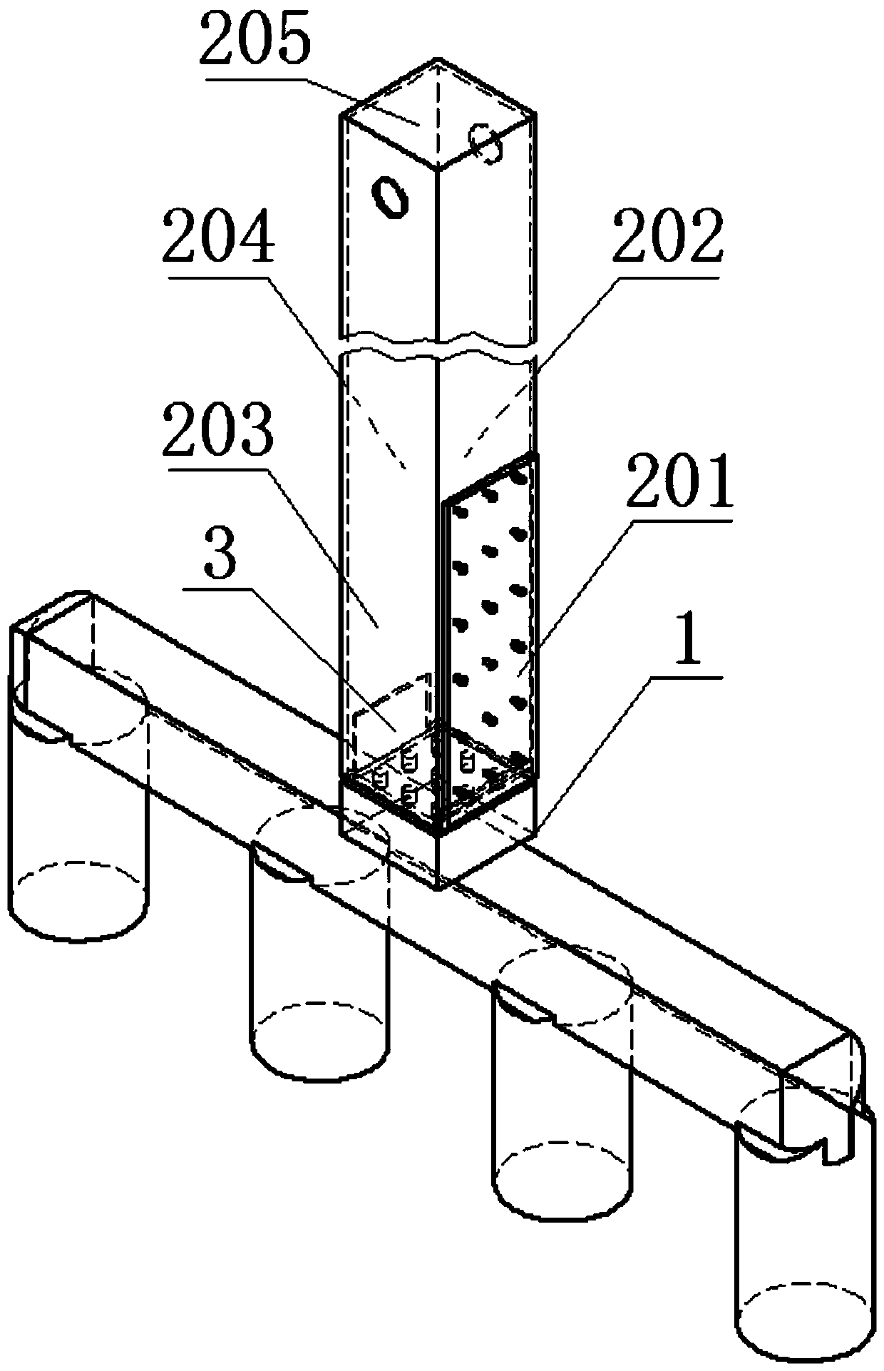
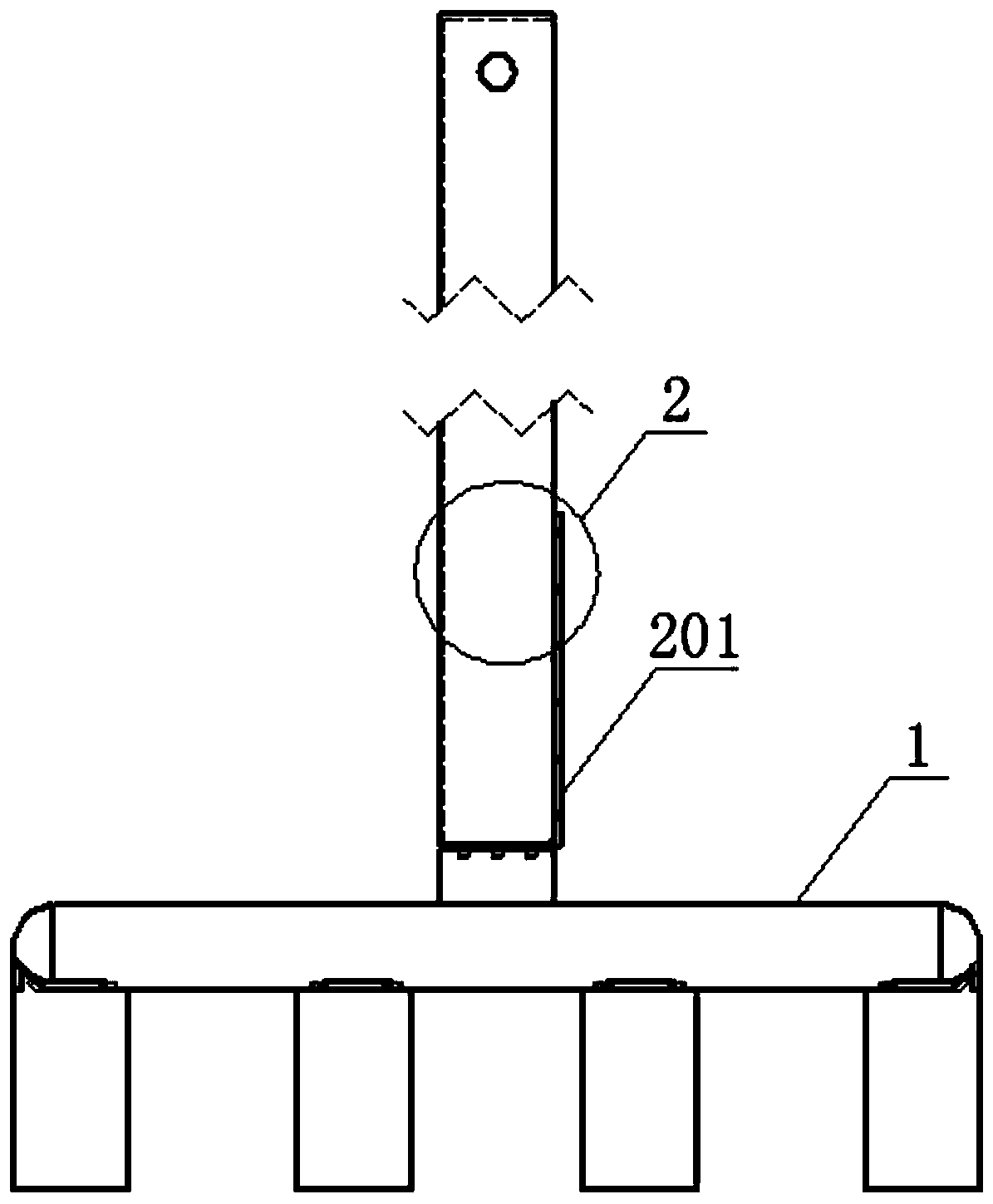
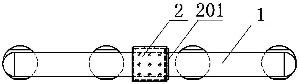
[0022] A kind of anodized steel claw guide rod set, such as figure 1 , figure 2 , image 3 and Figure 4 As shown, including the anode steel claw guide rod 2 and the anode steel claw 1, the anode steel claw guide rod 2 is provided with a hoisting part, and a good conductor plate 201 with a thickness of 22 mm is used (the thickness of the good conductor plate 201 in this embodiment is selected to be 22mm copper plate) and four steel plates (202, 203, 204, 205) with a thickness of 8mm that meet the strength requirements form a frame structure with a hollow bottom as the anode steel claw guide rod 2 directly connected to the top surface of the anode steel claw 1; good conductor The plate 201 (copper plate) is attached to one side of the anode steel claw guide rod 2, the steel plates (202, 203, 204) are located on the other three sides of the anode steel claw guide rod 2, and the steel plate 205 is located on the top surface of the anode steel claw guide rod 2, wherein , the s...

Embodiment 2

[0028] An anode steel claw guide rod group, comprising an anode steel claw guide rod and an anode steel claw, a hoisting part is arranged on the anode steel claw guide rod, and a good conductor plate with a thickness of 25mm is used (in this embodiment, the thickness of the good conductor plate is selected to be 25mm copper alloy plate) and four steel plates with a thickness of 6mm that meet the strength requirements form a frame structure with a hollowed out bottom as the anode steel claw guide rod directly connected to the top surface of the anode steel claw; the copper alloy plate is attached to the anode steel claw guide On one side of the rod, the steel plates are located on the other three sides of the anode steel claw guide rod and the top surface of the anode steel claw guide rod, and the bottom of the steel plate and the bottom of the good conductor plate on the side of the anode steel claw guide rod are directly welded and connected to the top surface of the anode stee...

Embodiment 3

[0034] A kind of anode steel claw guide rod group, comprise anode steel claw guide rod and anode steel claw, the anode steel claw guide rod is provided with hoisting part, adopts a piece of silver plate that thickness is 15mm (that is, good conductor plate selects the silver plate that thickness is 15mm Plate) and three steel plates with a thickness of 12mm that meet the strength requirements enclose a rectangular frame structure with a hollowed out bottom as the anode steel claw guide rod directly connected to the top surface of the anode steel claw; the silver plate is attached to one side of the anode steel claw guide rod, and the steel plate It is located on the adjacent side of the silver plate and the top surface of the anodized steel claw guide rod, and the opposite side of the silver plate is hollowed out. When in use, the silver plate is connected to the busbar.

[0035] As preferably, the hoisting part is located on the top surface of the anode steel claw guide rod, ...


PUM

PropertyMeasurementUnit
thicknessaaaaaaaaaa
thicknessaaaaaaaaaa
thicknessaaaaaaaaaa

Abstract

The invention provides an anode steel claw guide rod set. The anode steel claw guide rod set comprises an anode steel claw guide rod and an anode steel claw. The anode steel claw guide rod is providedwith a hoisting part. A frame structure defined by a good conductor and steel plates meeting the strength requirement is adopted as the anode steel claw guide rod to be directly connected to the anode steel claw, and the good conductor plate is attached to one side face of the anode steel claw guide rod; and the anode steel claw guide rod is of the frame structure defined by the good conductor plate and the steel plates, wherein the bottom of the frame structure is hollow. The phenomenon of arc discharge cannot happen to the anode steel claw guide rod set, the service life is long, contact resistance is hardly achieved for the anode steel claw guide rod set, and electrical losses are few. The anode steel claw guide rod set is simple in structure, low in manufacturing cost and convenient to install. The anode steel claw guide rod set is adopted for aluminum electrolysis, and environment protection is facilitated; and connection between the anode steel claw guide rod and the anode steelclaw is firm and stable, the phenomena of falling-off and tearing cannot happen, aluminum materials can be greatly saved, and the material cost of the anode steel claw guide rod is greatly reduced.

Description

technical field [0001] The invention relates to an anode steel claw guide rod group. Background technique [0002] In the aluminum electrolytic production process, the anode steel claw guide rod group as a conductive unit plays a vital role in the uniformity of the current distribution in the electrolytic cell and the stability of the electrolyte system, and its working temperature is 400-900 ° C. The traditional anode guide rod set consists of an anode steel claw guide rod, an aluminum / steel explosive block and an anode steel claw. The anode steel claw is made of ordinary carbon steel, the anode steel claw guide rod is made of aluminum, and the anode steel claw guide rod is Connection with anodized steel claws by aluminum / steel explosive welding nuggets. For example, the anode guide rod set disclosed in CN2816054Y includes a steel column, a steel claw base, and an aluminum guide rod connected to the steel claw base through an explosion welding block, and the steel column a...

Claims


Application Information

Patent Timeline
Patent Type & Authority Patents(China)
IPC IPC(8): C25C3/12
CPCC25C3/12
Inventor 苏雷虹周策林茂春连成华闵爱武
Owner 重庆角鹿机械制造有限公司
Why Eureka
Try Eureka