
Small-size in-situ fatigue testing machine considering temperature gradient and driven by piezoelectric ceramic

A piezoelectric ceramic drive, fatigue testing machine technology, applied in the direction of strength characteristics, the use of repetitive force/pulse force to test the strength of materials, measuring devices, etc., can solve the problem that the temperature load cannot reflect the working environment of the material, the size of the hydraulic drive unit is large, It is difficult to achieve high-frequency loading and other problems, and achieve the effect of high energy utilization efficiency, avoiding energy loss and improving energy utilization efficiency

Inactive Publication Date: 2018-10-30
BEIHANG UNIV
View PDF6 Cites 9 Cited by
  • Summary
  • Abstract
  • Description
  • Claims
  • Application Information

AI Technical Summary

Problems solved by technology

Among them, the testing machines driven by electric motors generally have relatively stable loading and can provide large loads, but limited by the driving principle, it is difficult to achieve high-frequency loading, and the efficiency of fatigue tests is low and the test period is long; the principle of hydraulic drive It can realize high-frequency drive, but due to the large size of the hydraulic drive unit, it can only be used with a special scanning electron microscope, which has poor versatility
[0004] (2) The simulation of temperature load cannot reflect the real working environment of the material
[0005] (3) Large volume and complex structure
Existing hydraulically driven testing machines inevitably have the disadvantage of large volume, while in-situ testing machines driven by electric motors are usually equipped with gear boxes to switch between different loading rates, so testing machines generally have complex structures and high manufacturing costs

Method used


Image

  • Small-size in-situ fatigue testing machine considering temperature gradient and driven by piezoelectric ceramic
  • Small-size in-situ fatigue testing machine considering temperature gradient and driven by piezoelectric ceramic

Examples


Embodiment Construction

[0022] The present invention will be further described below in conjunction with the accompanying drawings and embodiments.

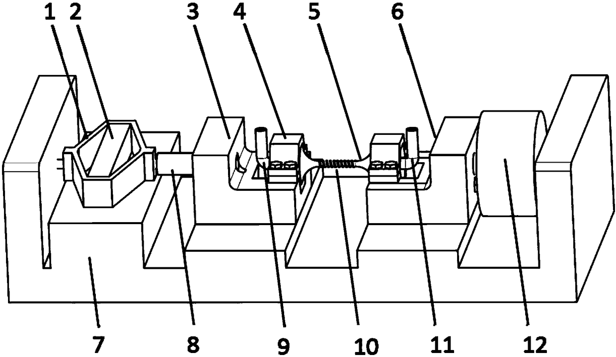
[0023] The invention provides a small piezoelectric ceramic drive in-situ fatigue testing machine considering the temperature gradient, the specific structure is as follows figure 1 shown.

[0024] The base 7 is the supporting and positioning part of the whole testing machine, its two ends are fixed ends, and the two end faces are respectively provided with the threaded holes for connecting with the drive unit and the force sensor 12, and the two threaded holes are coaxial; the middle part is Three positioning bosses with different heights are respectively used to support the drive unit, the output shaft clamp 3 and the force sensor clamp 6 .

[0025] The hollow fatigue test piece 5 is fixed between the output shaft clamp 3 and the force sensor clamp 6 through the clamp 4 . The drive unit composed of the flexible hinge amplifying mechanism 1 and the p...


PUM


Abstract

The invention provides a small-size in-situ fatigue testing machine considering a temperature gradient and driven by piezoelectric ceramic. The piezoelectric ceramic and a flexible hinge amplifying structure are adopted to form a driving unit, the inverse piezoelectric effect of the piezoelectric ceramic is utilized to generate high-frequency mechanical vibration, and after the high-frequency mechanical vibration is amplified by the flexible hinge amplifying structure, high-frequency fatigue load is applied on a test piece. When a heating resistor coil is heating the outside of the test piece,cooling air is led into the hollow test piece to cool the inside, so that simulation of the temperature gradient is realized. A force sensor is used for monitoring magnitude of the load on the test piece, and a closed-loop control system is used for adjusting input voltage of the piezoelectric ceramic according to the magnitude so as to control the applied load on the test piece. The small-size in-situ fatigue testing machine is simple in structure, small in size, high in working frequency, capable of simulating the temperature gradient, precise in loading and convenient to use in cooperationwith a scanning electron microscope for the in-situ fatigue test.

Description

technical field [0001] The invention relates to the technical field of material fatigue testing, in particular to a high-frequency in-situ fatigue testing machine based on piezoelectric ceramic loading. Background technique [0002] Materials are the basis for the development of various industries, and the development of materials is an important symbol of technological development and social progress, and the research and development of materials cannot be separated from the continuous innovation of testing methods. The traditional material testing method usually uses a universal testing machine to observe the material macroscopically. With the development of microscopic observation methods represented by scanning electron microscopy, the microstructure of materials has been revealed. In-situ testing of the mechanical properties of materials from the microscopic point of view to explore the microstructure evolution characteristics and failure mechanisms of materials under ...

Claims


Application Information

Patent Timeline
Patent Type & Authority Applications(China)
IPC IPC(8): G01N3/38G01N3/02
CPCG01N3/02G01N3/38G01N2203/0005G01N2203/0051G01N2203/0222
Inventor 闫晓军秦晓宇黄大伟丁水汀张小勇漆明净
Owner BEIHANG UNIV
Learn More