Testing method for thermal conductivity of phase change energy storage material

A technology of phase-change energy storage materials and testing methods, which is applied in the field of phase-change energy storage materials, can solve problems such as dehydration, difficulty in accurate measurement, and difficulty in preparing samples to be tested, so as to ensure stability and reliability Effect

Active Publication Date: 2018-10-30
QINGHAI INST OF SALT LAKES OF CHINESE ACAD OF SCI
View PDF7 Cites 11 Cited by
  • Summary
  • Abstract
  • Description
  • Claims
  • Application Information

AI Technical Summary

Problems solved by technology

The test methods of thermal conductivity of materials commonly used in laboratories include steady-state hot plate method and laser flash method. Steady-state methods (such as flat plate steady-state method, protected hot method) needs to process the sample into a certain sample specification (such as a certain size of square, cylinder, etc.), and some even have high requirements for the flatness of the sample surface; some dynamic methods (such as the transient hot wire method) although the sample There is no requirement in the specifications, but it can only accurately test the thermal conductivity of liquid and gas samples, and the deviation is relatively large when testing solid samples; The conductivity test did not take into account the impact of a large degree of subcooling (>15°C) on the test, which is unavoid

Method used


Image

  • Testing method for thermal conductivity of phase change energy storage material
  • Testing method for thermal conductivity of phase change energy storage material
  • Testing method for thermal conductivity of phase change energy storage material

Examples


Embodiment 1

[0083] The purpose of this embodiment is to measure the CaCl in the cooling crystallization process. 2 ·6H 2 O at 29.2°C (i.e. the temperature to be measured T 0 ) at the thermal conductivity.

[0084] Specifically, the following steps are used for determination:

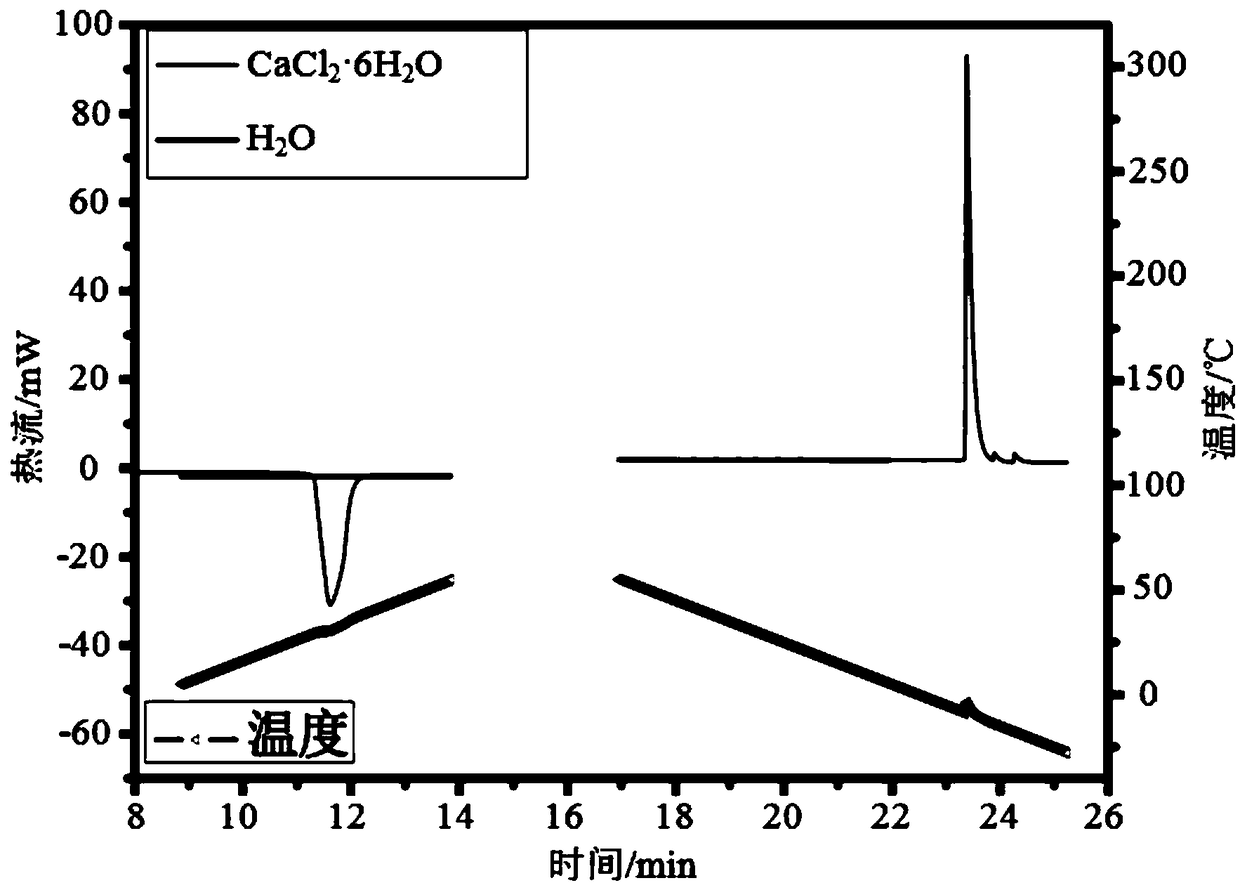
[0085] First, use DSC to test the empty sample pan (i.e. with a blank crucible as the background), water (m(H 2 O)=5.705mg) and CaCl 2 ·6H 2 O(m(Sam)=4.190mg) heat flow P(Bla), P(H 2 O) and P(Sam), the cooling rate is 10°C / min; the heat flow test results are as follows image 3 shown.

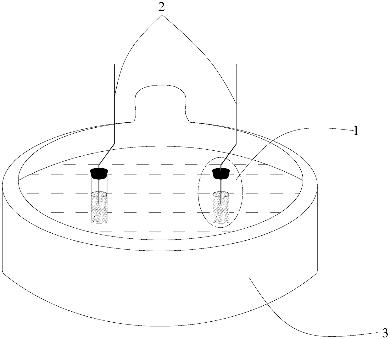
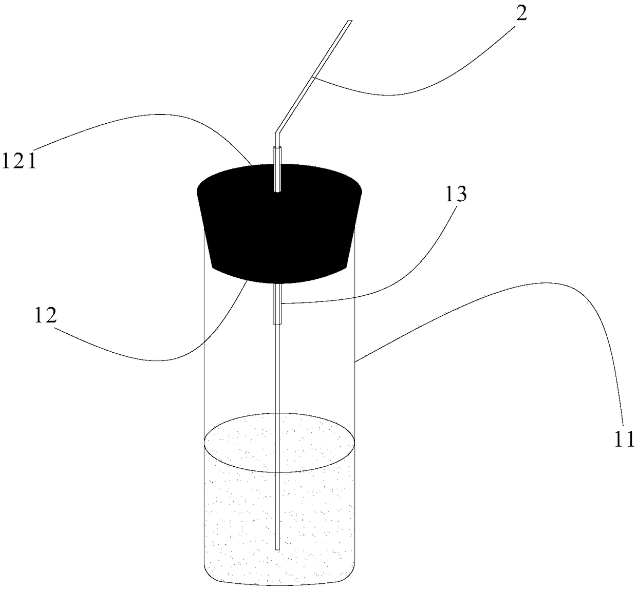
[0086] Then, 80mL of water (m'(H 2 O)=80.02g) and CaCl 2 ·6H 2 O(m'(Sam)=119.05g) were placed in figure 2 In the shown test tube 11, the test tube 11 is first placed in an ice-water bath, and shaken to make it crystallize at a temperature greater than 0°C (ice-water bath), CaCl 2 ·6H 2 Immediately after the O started to crystallize it was transferred to a 25 °C figure 1 In the water bath shown, and keep the water level...

Embodiment 2

[0091] The purpose of this embodiment is to measure the CaCl in the heating and melting process. 2 ·6H 2 O at 28.9°C (i.e. the temperature to be measured T 0 ) at the thermal conductivity.

[0092] Specifically, the following steps are used for determination:

[0093] First, use DSC to test the empty sample pan (i.e. with a blank crucible as the background), water (m(H 2 O)=5.705mg) and CaCl 2 ·6H 2 O(m(Sam)=4.190mg) heat flow P(Bla), P(H) heated between 30°C and 35°C 2 O) and P(Sam), the heating rate is 10°C / min; the heat flow test results are as follows image 3 shown.

[0094] Then, 80mL of water (m'(H 2 O)=80.02g) and CaCl 2 ·6H 2 O(m'(Sam)=119.05g) were placed in figure 2 In the test tube 11 shown, put the test tube 11 in a temperature of 35°C figure 1 In the water bath shown, and keep the water level line of the water bath and the water and CaCl in the test tube 2 ·6H 2 The surface of O is flat, water and CaCl are measured 2 ·6H 2 The temperature rise cu...

Embodiment 3

[0102] The purpose of this embodiment is to measure the CaCl in the heating process 2 ·6H 2 O liquid at 32.3 ℃ (that is, the temperature T to be measured 0 ) at the thermal conductivity.

[0103] Specifically, the following steps are used for determination:

[0104] First, use DSC to test the empty sample pan (i.e. with a blank crucible as the background), water (m(H 2 O)=5.705mg) and CaCl 2 ·6H 2 O(m(Sam)=7.590mg) heat flow P(Bla), P(H) heated between 29.5℃~35.0℃ 2 O) and P(Sam), the heating rate is 5°C / min; the heat flow test results are as follows Figure 5 and Image 6 shown. from Figure 5 and Image 6 It can be known that P(H 2 O)-P(Bla)=-1.863mW, P(Sam)-P(Bla)=-1.411mW; and it can be known from Example 2 that CaCl 2 ·6H 2 The average phase transition temperature of O in the heating process is 28.95°C, thus, the temperature T to be measured in this embodiment 0 With the sample to be tested CaCl 2 ·6H 2 The phase transition temperature T(Sam) of O is incon...


PUM

PropertyMeasurementUnit
Thermal conductivityaaaaaaaaaa

Abstract

The invention provides a testing method for the thermal conductivity of a phase change energy storage material. The testing method comprises the following steps: S1, respectively measuring the heat flows P (Sam) of a background, water and a sample to be tested in the temperature range of T1-T2 by using a scanning differential calorimeter; S2, assembling a heating/cooling curve tester, respectivelytesting heating curves or cooling curves of the water and the sample to be tested by using the rising/cooling curve tester, and according to whether the temperature T0 to be tested is equal to the phase change temperature T (Sam) as well as a heating melting process or a cooling crystallization process, calculating the thermal conductivity lambda (Sam) of the sample to be tested at the temperature T0 to be tested through an Equation 1 or 2 or 3. The testing method is a method proposed on the basis of the thermal conductivity law (Fourier's law), has no special requirement on the shape of thesample to be tested, and is applicable to thermal conductivity testing of solid-state and liquid-state samples and even a sample during phase change; especially, by the testing method, a great convenience is brought to thermal conductivity testing and enhanced thermal conductivity research of a room temperature PCM.

Description

technical field [0001] The invention belongs to the technical field of phase-change energy storage materials, and specifically relates to a method for testing the thermal conductivity of phase-change energy storage materials. Background technique [0002] The thermal conductivity of phase change materials (PCM) at room temperature in the working temperature range directly determines its temperature control efficiency, so the test of its thermal conductivity is of great importance for the determination of temperature control efficiency and thermal conductivity enhancement research. significance. [0003] The current international general standards for determining the thermal conductivity of materials are ASTM-D5470, ASTM-E1461, and ASTM-E1530 of the American Society for Testing and Materials (ASTM); The data differ greatly. [0004] ASTM-D5470, the thermal conductivity test standard is a test method for the heat transfer characteristics of thermally conductive electrical in...

Claims


Application Information

Patent Timeline
IPC IPC(8): G01N25/20G01N25/18
CPCG01N25/18G01N25/20
Inventor 申月周园海春喜曾金波孙艳霞李翔任秀峰
Owner QINGHAI INST OF SALT LAKES OF CHINESE ACAD OF SCI
Why Eureka
Try Eureka