Ultrasonic grinding device for gear

An ultrasonic and grinding technology, used in gear tooth manufacturing devices, belts/chains/gears, gear teeth, etc., can solve the problems of complex gear grinding process, achieve good economic benefits, prevent dust from entering, and improve flexibility Effect

Pending Publication Date: 2018-11-06
HENAN POLYTECHNIC UNIV
View PDF5 Cites 6 Cited by
  • Summary
  • Abstract
  • Description
  • Claims
  • Application Information

AI Technical Summary

Problems solved by technology

Due to the relative complexity of the gear grinding process, there are few reports on the design of ultrasonic gear grinding devices

Method used


Image

  • Ultrasonic grinding device for gear
  • Ultrasonic grinding device for gear
  • Ultrasonic grinding device for gear

Examples


Embodiment 1

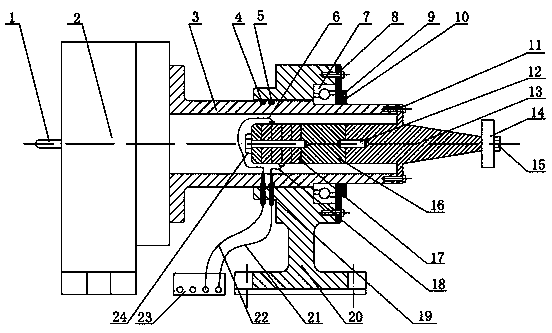
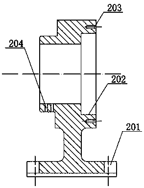
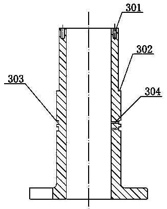
[0028] Embodiment one: see Figure 1-Figure 4 , in the figure, 1-handle, 2-rotary indexing device, 3-rotary hollow shaft, 4-rubber sleeve, 5-conductive copper ring, 6-first wire, 7-angular contact bearing, 8-connecting bolt, 9 -Bearing end cover, 10-Felt ring oil seal, 11-Screw, 12-Stud bolt, 13-Amplifier, 14-Gear workpiece, 15-Lock nut, 16-Vibrating rod, 17-Piezoelectric ceramic sheet , 18-second wire, 19-electric brush, 20-fixed base, 21-second connecting wire, 22-first connecting wire, 23-ultrasonic generator, 24-connecting bolt, 201-U-shaped groove, 202- Bearing groove, 203-threaded hole, 204-electric brush hole, 301-threaded hole, 302-shaft shoulder, 303-groove, 304-threading hole.

[0029] The fixed base 20 of the gear ultrasonic grinding device is provided with two U-shaped grooves 201 to connect with the workbench, the base of the fixed base 20 is provided with a groove 202 for fixing the bearing, and the right end surface of the fixed base 20 is provided along the ci...

Embodiment 2

[0034] Embodiment two: see Figure 5 , Figure 7-Figure 9, 1-handle, 2-rotary indexing device, 3-rotary hollow shaft, 9-angular contact bearing, 10-connecting bolt, 11-bearing end cover, 12-felt ring oil seal, 13-connecting bolt, 14-double head Bolt, 15-horn, 16-gear workpiece, 17-lock nut, 18-vibration rod, 19-piezoelectric ceramic sheet, 20-wire, 21-fixed base, 22-connecting line, 23-ultrasonic generator Device, 24-connecting bolts, 34-fixing bolts, 35-outer aluminum disc seat, 36-outer coil disc, 37-inner coil disc, 38-inner aluminum disc seat, 201-U-shaped groove, 202-bearing groove, 203-threaded hole, 205-aluminum disc hole, 301-bolt hole, 302-positioning step, 305-threading hole, 306-threaded hole.

[0035] The gear ultrasonic grinding device is composed of a fixed base, a gear workpiece rotation system, an ultrasonic vibration system, an external support fixing system and an ultrasonic power supply. The bottom of the fixed base 20 is provided with two U-shaped groove...

Embodiment 3

[0041] Embodiment three: see Figure 6 , in the figure, 25-variable frequency motor, 26-connecting plate, 27-motor flange, 28-fixed flange, this embodiment is basically the same as Embodiment 1, the similarities will not be repeated, the difference lies in: rotation One end of the hollow shaft 3 is connected with the fixed flange, and the output shaft of the variable frequency motor 25 is connected with the motor flange through a key, and the motor flange is connected with the fixed flange through connecting bolts.

[0042] Driven by the frequency conversion motor 25 to rotate at high speed, it is suitable for precision grinding of the outer circle of disc or cylindrical gear workpieces; by adjusting the frequency conversion motor 25 to change the rotation speed of disc or cylindrical workpieces 16, the grinding of discs or cylindrical workpieces can be realized. Or precision grinding of the outer circle of cylindrical gear workpieces.


PUM


Abstract

The invention discloses an ultrasonic grinding device for a gear. The ultrasonic grinding device comprises a rotary hollow shaft and a fixed base. The rotary hollow shaft is mounted in a penetrating hole in the fixed base in a sleeved mode, the rotary hollow shaft and the penetrating hole are rotationally connected, and one end of the rotary hollow shaft is fixedly connected with a connecting flange of an amplitude-change pole. A gear workpiece is fixed to the small end of the amplitude-change pole. The large end of the amplitude-change pole is located in the rotary hollow shaft and sequentially and fixedly connected with a vibration transmission pole, piezoelectric ceramic and an electrode slice. The piezoelectric ceramic and the electrode slice are connected with an ultrasonic generatorthrough an electric conduction mechanism. The other end of the rotary hollow shaft is connected with a rotary indexing device or a variable frequency motor. According to the ultrasonic grinding device, a gear ultrasonic vibration technology and a gear forming grinding technology are combined, ultrasonic grinding of the gear is achieved, the service life of a grinding wheel can be prolonged, the roughness of a tooth face is reduced, the machining precision of the gear is improved, the microscopic morphology of the tooth face is improved, and accordingly the anti-fatigue ability of the gear is improved.

Description

Technical field: [0001] The invention relates to gear precision machining equipment, in particular to a gear ultrasonic grinding device. Background technique: [0002] Gears play a decisive role in the system of transmitting motion and power. At present, the high-speed development of high-end equipment such as high-speed transportation, aerospace, and new energy requires more and more gears. Working under the conditions of high / low temperature and rain / sewage corrosion, at the same time bear the wheel-rail impact load generated by the line, the alternating load caused by the train's starting acceleration and braking deceleration, so more changes are made to the service performance and service life of the gear. High and even demanding requirements. Therefore, how to manufacture high-performance and long-life gears that serve under complex working conditions has become an important challenge for the innovation of mechanical equipment and the development of high-end equipment ...

Claims


Application Information

Patent Timeline
Patent Type & Authority Applications(China)
IPC IPC(8): B23F19/02B23F23/00
CPCB23F19/02B23F23/00
Inventor 赵波别文博高国富向道辉焦锋李章东赵重阳王晓博
Owner HENAN POLYTECHNIC UNIV
Why Eureka
Try Eureka