Nitrogen oxide ultralow emission system, emission energy saving device and flue gas waste heat recoverer
A technology of flue gas waste heat and energy-saving device, which is applied to water heaters, preheating, greenhouse gas reduction, etc. , The effect of short construction period and convenient operation
- Summary
- Abstract
- Description
- Claims
- Application Information
AI Technical Summary
Problems solved by technology
Method used
Image

Examples
Embodiment 1
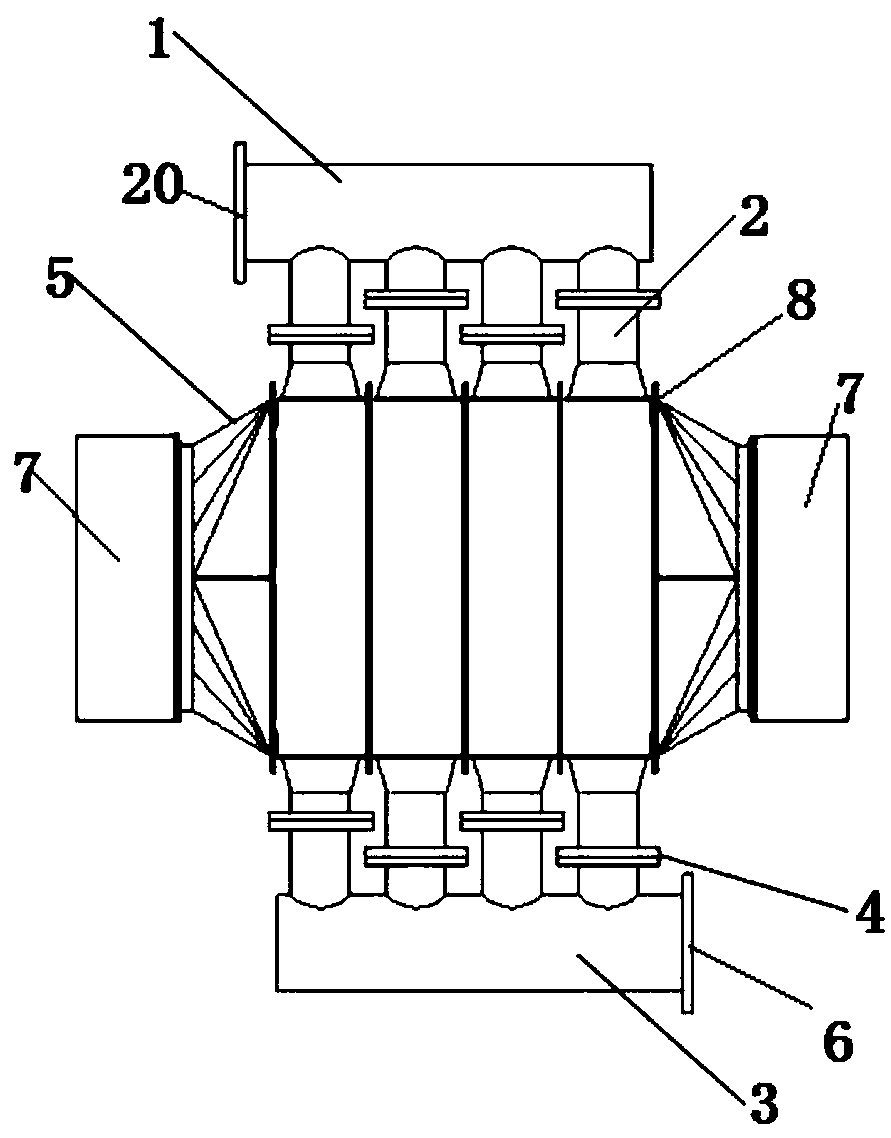
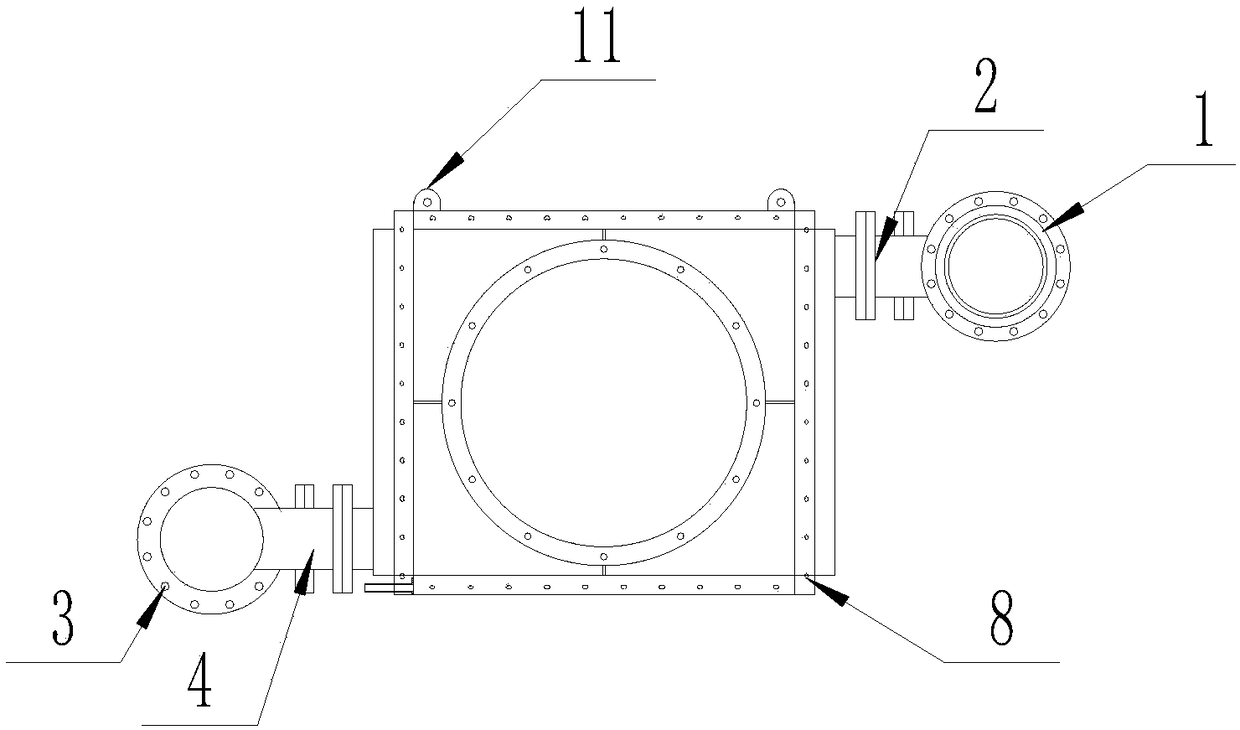
[0037] Such as Figure 2-5 The shown flue gas waste heat recovery device includes a total water inlet pipe 1, a branch water inlet pipe 2, a total water outlet pipe 3, a discharging water pipe 4, a connecting flange 5, an adapter pipe 7 and a waste heat recovery unit. The waste heat recovery unit includes a base frame 8, a base tube 9 and a fin 10; the base frame 8 is a set of frame structures with opposite sides open, and the relatively open sides of the base frame 8 are connected to flanges 5 and The adapter tube 7 is connected, and the fin 10 is fixedly wound on the outer side wall of the base tube 9. The base tube 9 is arranged in the base frame 8; the upper and lower bottom surfaces of the base frame 8 are respectively provided with through holes, and the base tube 9 The upper end of the base pipe passes through the opening on the bottom surface of the base frame 8 and is connected to one end of the branch water inlet pipe 2. The other end of the branch water pipe 2 is conn...
Embodiment 2
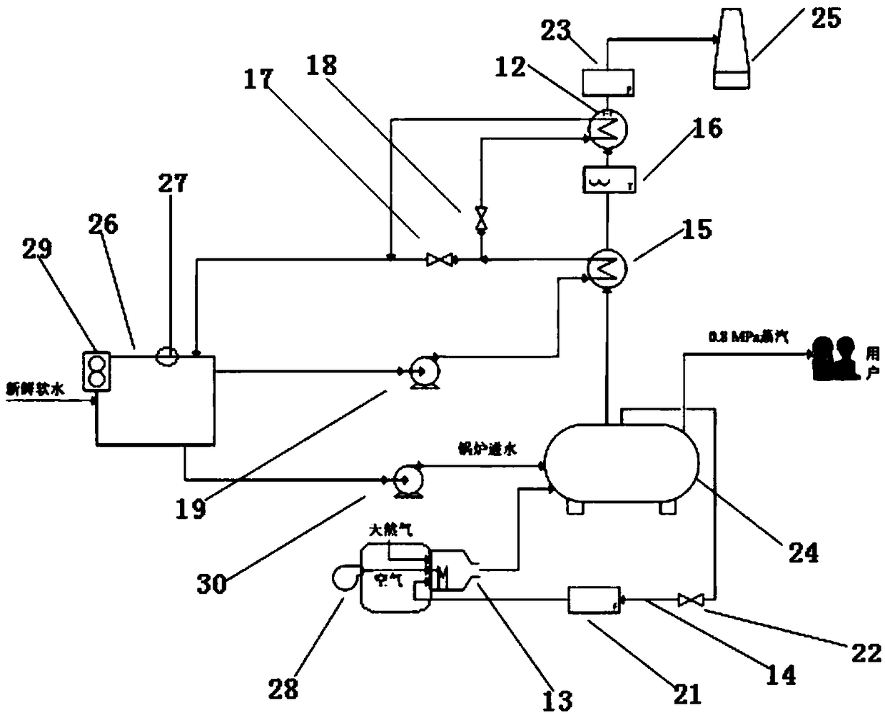
[0044] Such as Figure 1-Figure 5 An energy-saving emission device is shown, which includes at least a flue gas waste heat recovery device 12, and also includes an economizer 15, a low-nitrogen burner 13, a mixing box 28 and a flue gas external circulation pipe 14, wherein the economizer 15 has an inlet Water outlet and water outlet, the water outlet of the economizer 15 is connected to the main water inlet pipe 1 of the flue gas waste heat recovery device 12; the economizer 15 also has a flue gas inlet and a flue gas outlet, and the flue gas outlet of the economizer 15 is connected with The flue gas waste heat recovery device 12 has a flue gas inlet connected, and the flue gas waste heat recovery device 12 exhausts flue gas. The low-nitrogen burner 13 has a flue gas inlet and a flue gas outlet, and the low-nitrogen burner 13 has a flue gas inlet. The mixing box 28 is connected to one end of the flue gas external circulation pipe 14.
[0045] Preferably, it further includes a wat...
Embodiment 3
[0048] Such as figure 1 The shown energy-saving emission device differs from Embodiment 2 in that it also includes a control unit, which consists of a thermal resistor 16, a pressure transmitter 23, a water outlet valve 17, a water inlet valve 18, a flow meter 21, and a flow rate. The regulating valve 22, the feed water pump 19 and the DCS control system are composed. The DCS control system is connected with a thermal resistance 16 wire connected between the economizer 15 and the flue gas waste heat recovery device 12; the pressure transmitter 23 is set in the flue gas waste heat recovery The pressure transmitter 23 is also connected to the DCS control system line on the exhaust port of the device 12; the water inlet of the water outlet valve 17 is connected with the water outlet of the economizer 15, and the water outlet of the water outlet valve 17 is connected to the exhaust heat recovery device 12 of the flue gas. The main water outlet pipe 1 is connected; the water inlet va...
PUM
 Abstract
Description
Claims
Application Information
 - R&D
- Intellectual Property
- Life Sciences
- Materials
- Tech Scout
- Unparalleled Data Quality
- Higher Quality Content
- 60% Fewer Hallucinations
Browse by: Latest US Patents, China's latest patents, Technical Efficacy Thesaurus, Application Domain, Technology Topic, Popular Technical Reports.
© 2025 PatSnap. All rights reserved.Legal|Privacy policy|Modern Slavery Act Transparency Statement|Sitemap|About US| Contact US: help@patsnap.com