Foreign body manual removal method of laser foreign body removal device

A technology for removing foreign objects and lasers, applied in overhead lines/cable equipment, etc., can solve the problems of complex control, complex environment, labor and material resources, etc., and achieve the effect of improving operation accuracy, high control accuracy and high cutting efficiency.

Inactive Publication Date: 2018-11-06
NANJING UNIV OF SCI & TECH
View PDF0 Cites 8 Cited by
  • Summary
  • Abstract
  • Description
  • Claims
  • Application Information

AI Technical Summary

Problems solved by technology

[0002] The environment along the overhead power transmission line is complicated. Floating foreign objects such as kites and kite lines, agricultural plastic sheets, advertising cloth, and sunshade nets are often entangled on the transmission lines, resulting in tripping, power outages or line damage, which has caused great harm to the power system and society. economic loss
[0003] At present, there are two main methods for removing foreign matter on transmission lines. One is to remove the foreign matter on the tower by the staff, which requires climbing towers, wiring, high-voltage high-altitude operations, high difficulty, high risk, long time-consuming, and power outage opera...

Method used


Image

  • Foreign body manual removal method of laser foreign body removal device
  • Foreign body manual removal method of laser foreign body removal device
  • Foreign body manual removal method of laser foreign body removal device

Examples


Embodiment Construction

[0026] The present invention will be further described below in conjunction with the accompanying drawings of the specification.

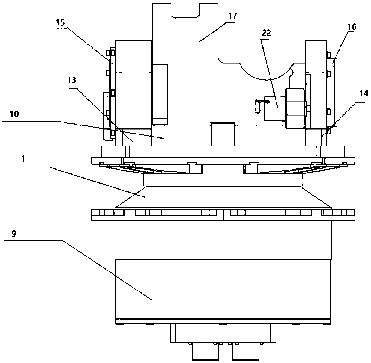
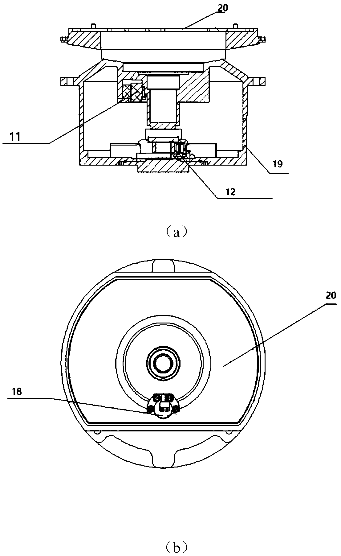
[0027] Such as figure 1 Shown is a schematic diagram of the assembly structure of the laser foreign body removal device using the method of the present invention. The device includes a turntable 1, a laser component 2, a base 3, a power supply system, an input and output device, a control system, a communication module, and a vision sensor 8 (preferably HD Industrial camera), where the turntable 1 includes an orientation component 9 and a tilt component 10. The azimuth component 9 is installed above the base 3, including the azimuth torque motor 11, the azimuth angle measuring device (resolver transmitter or electronic encoder) 12; the pitch component 10 is installed above the azimuth component 9, including bearing seat 13 and bearing seat 2. 14. Pitching torque motor 15; laser component 2 includes laser emitting head 21 and laser control box 25, lase...


PUM


Abstract

The invention discloses a foreign body manual removal method of a laser foreign body removal device. The foreign body manual removal method of the laser foreign body removal device comprises the following steps: a visual sensor collects current image information and a display displays the current image information; a control system carries out image recognition, obtains the winding information ofthe foreign body point, calculates and converts the winding information of the foreign body point into angular coordinates, sends an instruction to a turntable to make it rotate, and traces the foreign body winding point; a cutting mode is entered according to the information of an input device; the control system calculates the angle information and calculates the corresponding turntable instructions at each time according to the received cutting direction, cutting speed instruction and the current pixel information; and the laser part sends a laser, the control system sends the correspondingangle instruction to the turntable, so as to control the turntable to drive the laser part to rotate, and then complete the cutting task. According to the foreign body manual removal method of the laser foreign body removal device, the object position is displayed through the visual sensor, and the laser foreign body removal device is controlled through a user end on the basis of automatic tracing; therefore, the adaptability of the device to complex foreign bodies is improved, and the control accuracy and cutting efficiency are improved.

Description

Technical field [0001] The invention relates to the field of intelligent removal of foreign objects in high-voltage transmission lines, and specifically, a method for manually removing foreign objects with a laser foreign object removal device. Background technique [0002] The environment along the overhead transmission lines is complicated. Floating foreign objects such as kites and kite lines, agricultural plastic sheets, advertising cloths, sunshade nets, etc. are often entangled on the transmission lines, resulting in line trips and power failures or line damage, which has caused great damage to the power system and society. Economic loss. [0003] At present, there are two main methods for removing foreign objects on transmission lines. One is for workers to go up to the tower to remove them, which requires climbing towers, wiring, high-voltage and high-altitude operations, which are difficult, risky, time-consuming, and power outage operations. Other shortcomings, consume a...

Claims


Application Information

Patent Timeline
IPC IPC(8): H02G1/02
CPCH02G1/02
Inventor 樊卫华文云郭健李胜姜珊郭烨黄紫霄董晟王艳琴韩宇
Owner NANJING UNIV OF SCI & TECH
Why Eureka
Try Eureka