Efficient and energy-saving reducing furnace chassis and polycrystalline silicon reducing furnace

A high-efficiency, energy-saving, reducing furnace technology, applied in silicon compounds, chemical instruments and methods, sustainable manufacturing/processing, etc., can solve problems such as poor quality, increased production costs, and large disturbances, and achieve consistent growth quality and improved Conversion rate, the effect of uniform gas field

Pending Publication Date: 2018-11-09
内蒙古通威高纯晶硅有限公司
View PDF5 Cites 0 Cited by
  • Summary
  • Abstract
  • Description
  • Claims
  • Application Information

AI Technical Summary

Problems solved by technology

[0004] However, in fact, with the increase in the number of rods in the polysilicon reduction furnace, the complex chemical reactions, mass transfer, heat transfer and other processes in the polysilicon reduction furnace have a great impact on the temperature field (temperature distribution) and gas field (gas concentration distribution) in the reaction furnace. and flow conditions) the degree of disturbance becomes larger, making it difficult for the raw material gas to be evenly distributed in the reduction furnace, the concentration of the raw material gas around some silicon cores is low, and the flow rate of the local reaction gas is too fast
In order to allow each silicon core to fully contact with the raw material gas for reaction, only an excessive amount of raw material gas can only be supplied, resulting in a low conversion rate of raw materials and the risk of furnace failure, resulting in increased production costs and poor quality

Method used


Image

  • Efficient and energy-saving reducing furnace chassis and polycrystalline silicon reducing furnace
  • Efficient and energy-saving reducing furnace chassis and polycrystalline silicon reducing furnace
  • Efficient and energy-saving reducing furnace chassis and polycrystalline silicon reducing furnace

Examples


Embodiment Construction

[0038] In order to enable those skilled in the art to better understand the technical solution of the present invention, the present invention will be further described in detail below in conjunction with the accompanying drawings and specific embodiments.

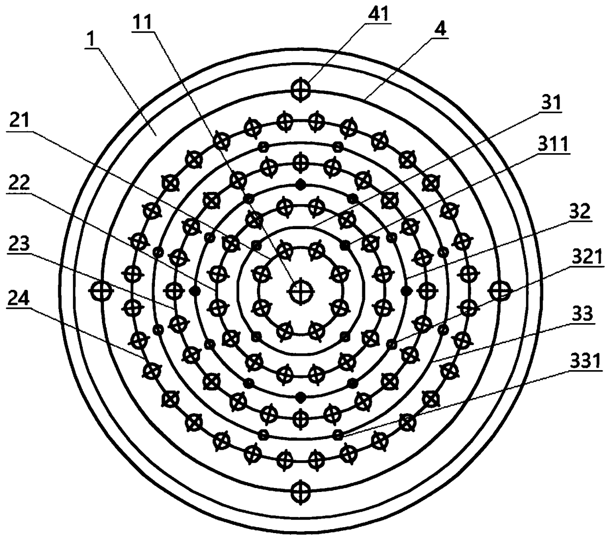
[0039] Please refer to figure 1 , the embodiment of the present invention provides a high-efficiency energy-saving reduction furnace chassis, including a chassis body 1, a central feeding port 11, 4 electrode ring layers and 3 feeding ring layers are arranged on the chassis body 1, and the electrode ring layers and The feeding ring layer is arranged at intervals with the central feeding port 11 as the center of the circle; from the inside to the outside are the first electrode ring layer 21, the first feeding ring layer 31, the second electrode ring layer 22, the second feeding ring layer 32, The third electrode ring layer 23 , the third feed ring layer 33 and the fourth electrode ring layer 24 .

[0040]The first electro...


PUM


Abstract

The invention discloses an efficient and energy-saving reducing furnace chassis. The efficient and energy-saving reducing furnace chassis comprises a chassis, wherein a central feeding hole is formedin the chassis, n electrode ring layers and n-1 feeding ring layers are arranged on the chassis, and n is an positive integer more than or equal to 4; the electrode ring layers and the feeding ring layers are arranged at intervals by taking the central feeding hole as a round center; each feeding ring layer is provided with at least four feeding holes; the nth electrode ring layer is provided with4n pairs of electrodes according to the counting of the electrode ring layers from inside to outside; each two adjacent electrodes of the same electrode ring layer are arranged in an equal interval manner; and a discharging ring layer is arranged outside the nth electrode ring layer and is provided with at least two discharging holes, and the two discharging holes are formed in the discharging ring layer in an equal interval manner. By redesigning the layout of the electrodes and feeding holes on and in the reducing furnace chassis, the temperature field and gas field for reaction in a reducing furnace are improved, and meanwhile, the raw material conversion rate is increased, and the production cost is lowered. The invention further provides a polycrystalline silicon reducing furnace including the efficient and energy-saving reducing furnace chassis.

Description

technical field [0001] The invention relates to the field of polysilicon production, in particular to a high-efficiency energy-saving reduction furnace chassis and a polysilicon reduction furnace. Background technique [0002] At present, the mainstream polysilicon production technology is the improved Siemens method: the silicon core connected to the electrode is used as the deposition substrate, and the high-purity trichlorohydrogen silicon is reduced and deposited in a hydrogen atmosphere to form polysilicon by using a high-temperature reduction process. [0003] Theoretically, the more electrode pairs in the polysilicon reduction furnace, that is, the more the number of silicon cores, the greater the output of polysilicon per furnace; at the same time, the more polysilicon cores per unit area, occupying the space of the gas, so in the same raw material Under the gas flow rate, the concentration of the trichlorosilane raw material per unit volume increases, so that the de...

Claims


Application Information

Patent Timeline
Patent Type & Authority Applications(China)
IPC IPC(8): C01B33/035
CPCC01B33/035Y02P20/10
Inventor 王亚萍甘居富彭中游书华罗周庹如刚张聪张杰余涛晏涛刘斌
Owner 内蒙古通威高纯晶硅有限公司
Why Eureka
Try Eureka