Laser-based wireless frequency transmission system and transmission device and transmission method thereof

A wireless frequency and transmission device technology, applied in the field of wireless frequency transmission system and its transmission device, can solve the problems of wireless laser phase jitter, achieve the effect of improving synchronization accuracy and reliability, and avoiding phase noise

Active Publication Date: 2018-11-13
ZTE CORP
View PDF8 Cites 4 Cited by
  • Summary
  • Abstract
  • Description
  • Claims
  • Application Information

AI Technical Summary

Problems solved by technology

[0007] In view of this, the purpose of the present invention is to provide a laser-based wireless frequency transmission system and its transmission device and transmission method to solve the phase jitter generated by wireless laser transmission in the air and the relative intensity noise caused by beam fluctuations, thereby improving freedom Synchronization Accuracy and Reliability of Space Radio Frequency Transmission

Method used


Image

  • Laser-based wireless frequency transmission system and transmission device and transmission method thereof
  • Laser-based wireless frequency transmission system and transmission device and transmission method thereof
  • Laser-based wireless frequency transmission system and transmission device and transmission method thereof

Examples


Embodiment 1

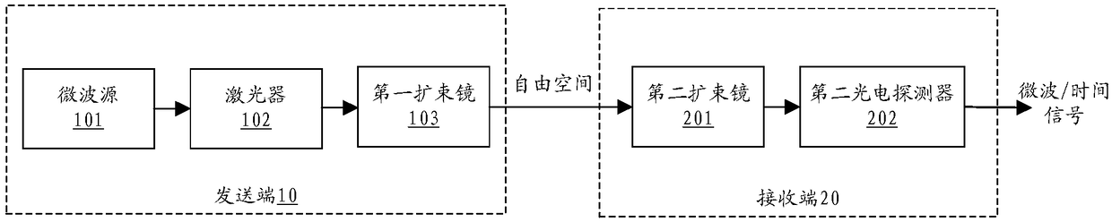
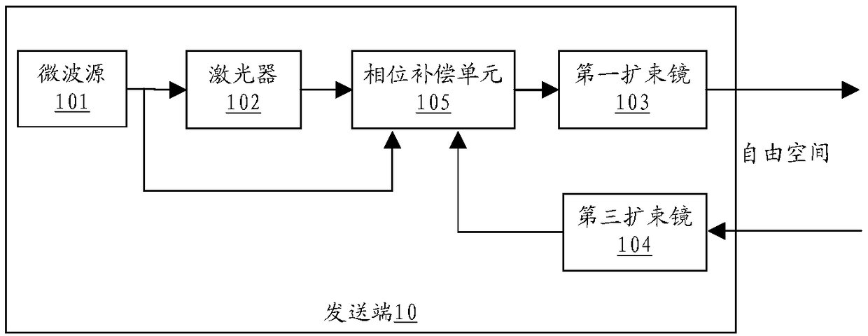
[0061] Such as figure 2 As shown, a laser-based wireless frequency transmission device provided by the embodiment of the present invention is applied to the transmitting end 10, including a microwave source 101, a laser 102, a first beam expander 103, a third beam expander 104, and a phase compensation unit 105. in:

[0062] The microwave source 101 is used to send a reference frequency signal.

[0063] Specifically, the microwave source 101 can generate a single-frequency radio frequency signal with extremely low phase noise, and is generally a voltage-controlled source, which is used to transmit a local reference frequency signal, and modulate the reference frequency signal to the laser 102 .

[0064] The laser 102 is used to generate a continuous laser signal to modulate a reference frequency signal.

[0065] Specifically, the laser 102 can generate a single-frequency continuous laser with tunable wavelength, provide a laser signal loaded with a reference frequency sign...

Embodiment 2

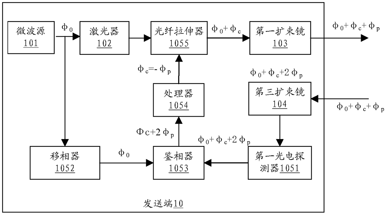
[0072] Such as image 3 As shown, a phase compensation unit 105 provided by the embodiment of the present invention can be further realized by a phase shifter 1051, a first photodetector 1052, a phase detector 1053, a processor 1054 and an optical fiber stretcher 1055, wherein:

[0073] The phase shifter 1051 is used to adjust the phase of the reference frequency signal and output it to the phase detector 1053 .

[0074] The first photodetector 1052 is used to demodulate the modulated microwave signal in the laser signal reflected by the receiving end 20 and output it to the phase detector 1052 .

[0075] The phase detector 1053 is configured to compare the phases of the reference frequency signal input by the phase shifter 1051 and the frequency signal input by the first photodetector 1052 , and output the phase error to the processor 1054 .

[0076] Specifically, the function of the phase detector 1053 is to extract the phase difference of the round-trip signal. In this emb...

Embodiment 3

[0088] Such as Figure 4 As shown, in a laser-based wireless frequency transmission device provided by an embodiment of the present invention, the fluctuation of the beam position causes the relative intensity noise generated when the beam is coupled, and the vibration of the transceiver optical platform, the beam expander, and the mirror causes the beam The amplitude fluctuation caused by the direction change, such as: the period of the fluctuation, the amplitude of the fluctuation, and whether the spot is deformed or not. In order to suppress the influence of beam fluctuations, a first beam stabilization unit 106 is added to the sending end 10 to directly eliminate beam fluctuations.

[0089] The first beam stabilizing unit 106 is configured to adjust the beam direction of the laser signal returned from the receiving end 20 to focus on the photocell of the first photodetector 1052 of the phase compensation unit 105 .

[0090] As a preferred embodiment, such as Figure 5 As...


PUM


Abstract

The invention discloses a laser-based wireless frequency transmission system and a transmission device and a transmission method thereof, and belongs to the technical field of frequency synchronization. The system comprises a transmitting end and at least one receiving end; the receiving end comprises a beam return unit for reflecting received partial laser signals back to the transmitting end; and the transmitting end further comprises at least one pair of third beam expanders and a phase compensation unit, wherein the third beam expanders are used for coupling the laser signals returned by the receiving end to the phase compensation unit, and the phase compensation unit is used for carrying out phase comparison on a reference frequency signal and a microwave signal modulated in the lasersignals reflected back by the receiving end in real time, and adjusting the phase of the laser signals according to a phase error. According to the laser-based wireless frequency transmission systemprovided by the invention, an active phase compensation link is introduced, so that the phase fluctuation caused by atmospheric turbulence, vibration and temperature fluctuation is suppressed, and thefrequency synchronization accuracy and reliability of a free space are improved.

Description

technical field [0001] The invention relates to the technical field of frequency synchronization, in particular to a laser-based wireless frequency transmission system, a transmission device and a transmission method thereof. Background technique [0002] High-precision time-frequency synchronization plays a very important role in modern scientific experiments and practical engineering applications. Its purpose is to synchronize the phase and time of reference frequency signal sources at two or more points separated by a certain distance. High-precision synchronization technology has a wide range of applications in communications, radar detection, telemetry, navigation systems, astronomical observations, and basic scientific research. [0003] In the application of multi-point synchronization system, the most used is the high-precision synchronization technology for frequency signal transmission. Currently commonly used frequency signal transmission methods include radio fr...

Claims


Application Information

Patent Timeline
Patent Type & Authority Applications(China)
IPC IPC(8): H04B10/11H04B10/50H04B10/548H04B10/67H04B10/69
CPCH04B10/11H04B10/503H04B10/548H04B10/67H04B10/697H04B10/50H04B10/69
Inventor 陈诗军侯冬龚翠玲陈大伟陈强王园园
Owner ZTE CORP
Why Eureka
Try Eureka