Axial split-phase magnetic suspension flywheel rotor gyroscopic effect inhibition method

A technology of axial phase separation and flywheel rotor, applied in special data processing applications, magnetic attraction or thrust holding devices, instruments, etc. Algorithm complexity and other issues

Active Publication Date: 2018-11-20
NANJING INST OF TECH
View PDF7 Cites 4 Cited by
  • Summary
  • Abstract
  • Description
  • Claims
  • Application Information

AI Technical Summary

Problems solved by technology

For example, the most widely used decentralized proportional-integral-derivative (PID) control ignores the coupling effect between degrees of freedom, and the control accuracy is low at high speeds; while various cross-feedback control algorithms mostly use Taylor linearization method to linearize the system model at the equilibrium point , so as to complete the feedback control, which is not robust to air gap changes; the adaptive feedback control method has good control accuracy and robustness, but the algorithm has a large amount of calculation and low real-time performance; the inverse system linearization decoupling algorithm The physical concept is clear and easy to implement, but it is easily affected by model and parameter changes. In practical applications, it is necessary to further design robust servo regulators, such as sliding mode control, H∞ control, μ synthesis, and linear quadratic (LQR) control , neural network, fuzzy control, etc., which makes the algorithm very complicated
Therefore, the existing gyro effect suppression methods have shortcomings in algorithm accuracy, simplicity, and robustness, and it is difficult to achieve satisfactory control effects in the actual application of complex high-speed maglev systems.

Method used


Image

  • Axial split-phase magnetic suspension flywheel rotor gyroscopic effect inhibition method
  • Axial split-phase magnetic suspension flywheel rotor gyroscopic effect inhibition method
  • Axial split-phase magnetic suspension flywheel rotor gyroscopic effect inhibition method

Examples


Embodiment

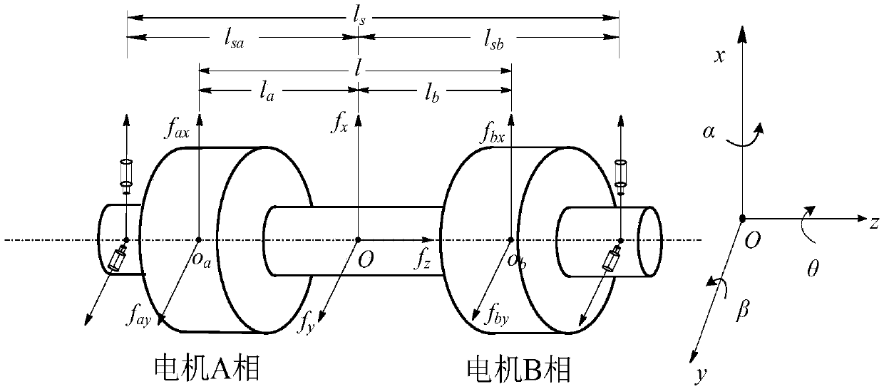
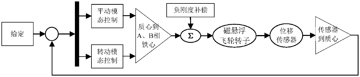
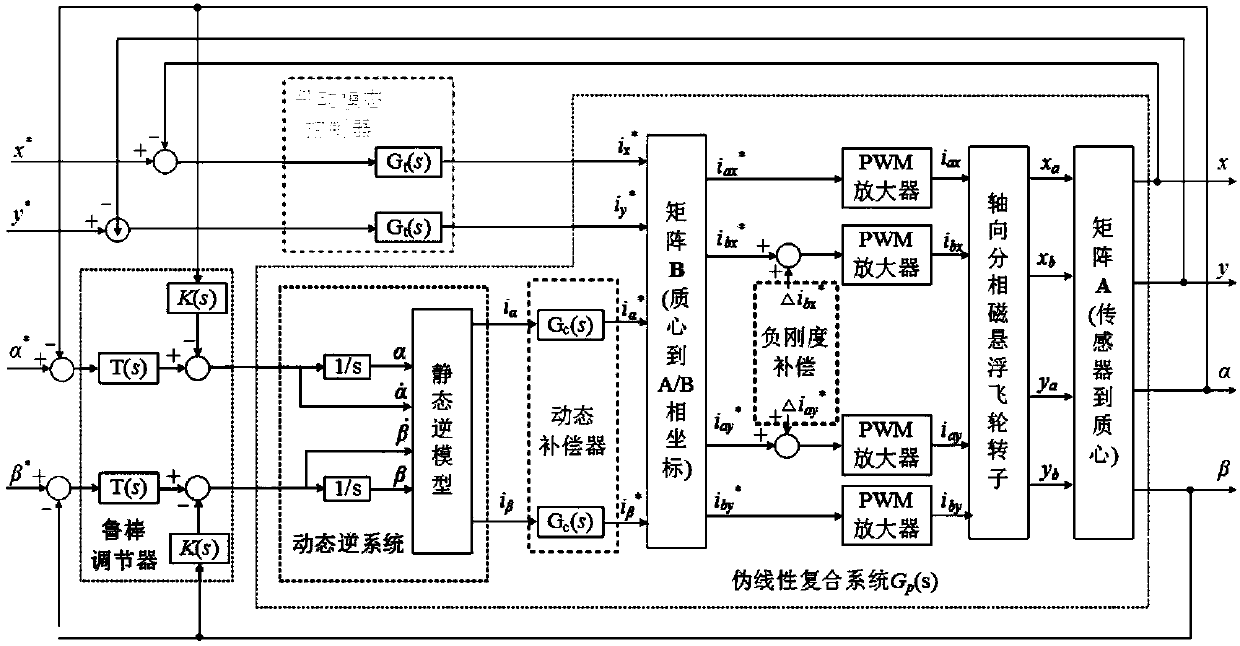
[0058] A method for suppressing the gyroscopic effect of an axially phase-separated magnetically suspended flywheel rotor according to an embodiment, first constructs an axially phase-separated magnetically suspended rotor dynamics model based on translational and rotational coordinate systems, and then uses decentralized control to realize translational and rotational mode solutions Then design the centralized control based on inverse system decoupling to realize the decoupling of nutation mode and precession mode, and finally design a robust servo regulator and dynamic compensator for the decoupled nonlinear system for system synthesis. The method of the embodiment combines decentralized control and centralized control to complete a gyro effect suppression algorithm for a magnetic levitation flywheel rotor based on modal decoupling, which can simplify the control algorithm and improve control accuracy and robustness at the same time.

[0059] A method for suppressing the gyro...


PUM


Abstract

The invention provides an axial split-phase magnetic suspension flywheel rotor gyroscopic effect inhibition method, and belongs to the technical field of magnetic suspension transmission. The method comprises the following steps: firstly, constructing an axial split-phase magnetic suspension rotor dynamic model on the basis of translational and rotational coordinate systems, and thereby realizingtranslational modal and rotational modal decoupling by adopting decentralized control; secondly, realizing nutation modal and precession modal decoupling based on centralized control of inverse systemdecoupling; and finally, performing system closed-loop integration on a decoupled nonlinear system through a robust servo regulator and a dynamic compensator. According to the axial split-phase magnetic suspension flywheel rotor gyroscopic effect inhibition method provided by the invention, the decentralized control and the centralized control are combined to complete a magnetic suspension flywheel rotor gyroscopic effect inhibition algorithm based on modal decoupling, thus a control algorithm can be simplified, and meanwhile, the control precision and the robustness are improved.

Description

technical field [0001] The invention relates to a method for suppressing the gyro effect of an axially phase-separated magnetic levitation flywheel rotor. Background technique [0002] The flywheel energy storage system is a physical energy storage device for electromechanical energy conversion. It has the advantages of large specific power, small size, long life, fast charging and discharging, clean and pollution-free, etc. It is a new type of energy storage with high research value and broad application prospects. technology. On the basis of fully retaining the high-speed and excellent characteristics of the switched reluctance motor, the magnetic levitation switched reluctance motor further improves the high-speed performance and operating efficiency of the motor through the active control of its own levitation force. Introducing it into the flywheel energy storage can realize the suspension support of the system with ultra-low power consumption and the integrated operat...

Claims


Application Information

Patent Timeline
Patent Type & Authority Applications(China)
IPC IPC(8): G06F17/50H02N15/00
CPCH02N15/00G06F30/20
Inventor 朱志莹孙玉坤郭旋朱金任元
Owner NANJING INST OF TECH
Why Eureka
Try Eureka