Treatment method of magnesium alloy melt

A processing method and technology for magnesium alloys, applied in the field of metal materials and metallurgy, can solve the problems of reduced refining effect, low stirring strength, influence on alloy composition, etc., and achieve the effects of uniform structure and composition, good processing effect and high processing efficiency.

Active Publication Date: 2018-11-23
NORTHEASTERN UNIV
View PDF9 Cites 10 Cited by
  • Summary
  • Abstract
  • Description
  • Claims
  • Application Information

AI Technical Summary

Problems solved by technology

Among them, although the melt superheating method can play a certain role in refinement, this method increases the oxidation loss and gas absorption of the magnesium melt, and increases the consumption of energy and crucible
Therefore, this method has been rarely used in production. By changing the casting process parameters before pouring or during the casting process, although it can have a certain refinement effect during the solidification process, it only has a refinement effect on the local area of ​​​​the product, and it is difficult to Achieve uniform refinement of the entire volume
The refinement method of adding alloy elements can significantly refine the solidification structure of magnesium alloys. At present, the addition of alloys is mainly rare earth elements, but the cost is relatively high. At the same time, new alloy elements will be introduced to affect the composition of the alloy.
Mechanical stirring of alloy melt, including contact and non-contact: contact stirring is easy to pollute the melt, and stirring can only be carried out in liquid state and cannot be used in the solidification process, so the refining effect is greatly reduced; non-contact Stirring (such as: magnetic field stirring) is the main method of melt treatment at present, but due to the small range of magnetic field skin effect, low stirring intensity, low utilization rate of magnetic energy, etc., it has not achieved a good treatment effect

Method used


Image

  • Treatment method of magnesium alloy melt
  • Treatment method of magnesium alloy melt
  • Treatment method of magnesium alloy melt

Examples


Embodiment 1

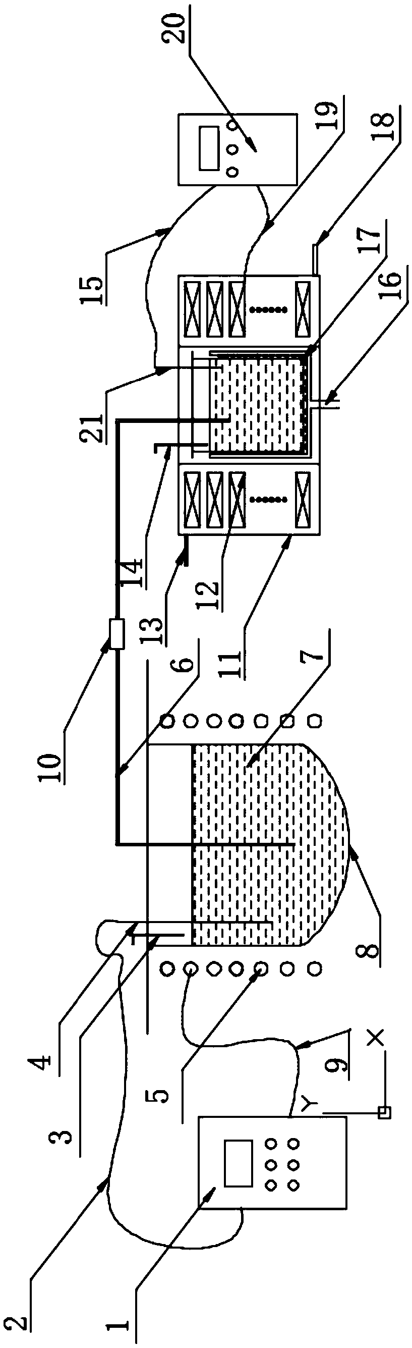
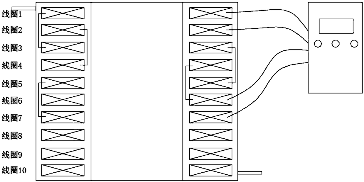
[0034] Place the 500Kg commercial magnesium alloy AZ80 material in a melting furnace to melt, and then refining for 40 minutes. After the refining, the melt is allowed to stand at 710°C; before the melt is processed, an electromagnetic generation system containing an electromagnetic coil set is installed The coil group is composed of 6 groups of coils. Connect coil 1, coil 3, and coil 5 in series to form a coil group and pass a sharp waveform pulse current with a frequency of 20Hz, current of 100A and a duty cycle of 50%; coil 2, coil 4, and coil 6 in series to form another coil group Parallel frequency is 20Hz, current is 100A with a sharp waveform pulse current with duty ratio of 50%, and the phase difference between the two coil groups is set to 90°C. Place the mold in an electromagnetic generation system with cooling function, then transfer the static melt to a mold with a cooling rate of 2°C / s, and start the electromagnetic generation system to process the alloy melt for 1...

Embodiment 2

[0037] Place the 500Kg commercial magnesium alloy AZ80 material in a melting furnace for melting, and then refining for 40 minutes. After the refining, the melt is allowed to stand at 710°C; before the melt is processed, an electromagnetic generation system containing an electromagnetic coil set is installed The coil group is composed of 6 groups of coils. Connect coil 1, coil 3, and coil 5 in series to form a coil group and pass a sharp waveform pulse current with a frequency of 20Hz, current of 100A and a duty cycle of 50%; coil 2, coil 4, and coil 6 in series to form another coil group The parallel frequency is 40Hz, the current is 150A with a sharp waveform pulse current with a duty cycle of 50%, and the phase difference between the two coil groups is set to 90°C. Place the mold in an electromagnetic generation system with cooling function, then transfer the static melt to a mold with a cooling rate of 2°C / s, and start the electromagnetic generation system to process the al...

Embodiment 3

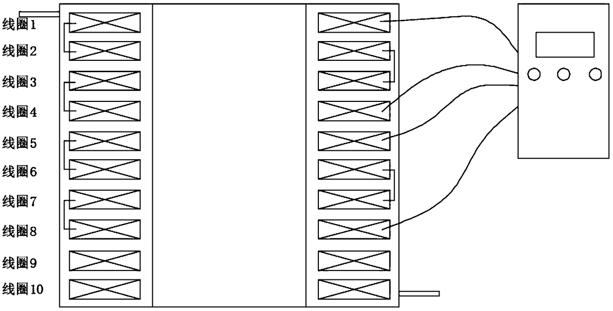
[0040] Place the 200Kg commercial magnesium alloy AZ80 material in a melting furnace for melting, and then refining for 20 minutes. After the refining, the melt is allowed to stand at 700°C; before the melt is processed, an electromagnetic generation system containing an electromagnetic coil set is installed The coil group is composed of 6 groups of coils. Connect coil 1, coil 2, and coil 3 in series to form a coil group and pass a sharp waveform pulse current with a frequency of 20Hz, current of 100A and a duty cycle of 60%; coil 4, coil 5, and coil 6 are connected in series to form another coil group The parallel frequency is 20Hz, the current is 100A with a sharp waveform pulse current with a duty ratio of 3%, and the phase difference between the two coil groups is set to 90°C. Place the mold in an electromagnetic generation system with cooling function, then transfer the static melt to a mold with a cooling rate of 30°C / s, and start the electromagnetic generation system to ...


PUM


Abstract

The invention belongs to the technical field of metal materials and metallurgy and in particular relates to a treatment method of a magnesium alloy melt. The treatment method comprises the following steps: putting a prepared magnesium alloy material into a melting furnace and melting; then carrying out refining; after the refining is finished, carrying out standing on the melt; before the melt istreated, setting pulse current, pulse frequency and pulse forms of an electromagnetic generation system containing an electromagnetic coil group, and phase difference parameters of current accessed into different coils; putting a mold system into the electromagnetic generation system with a cooling function; then transferring the melt subjected to the standing into the mold system with a cooling control device and treating the alloy melt by adopting the electromagnetic coil group; after melt treatment is finished, firstly closing the electromagnetic generation system; after condensing and cooling the melt through the cooling control device, closing the cooling control device of the mold system and taking out a casting ingot. The method is simple, easy to control and easy to control and hasno pollution, high treatment efficiency and a good treatment effect; the method can be used for treating in a whole process and is easily applied to industrial production.

Description

Technical field [0001] The invention belongs to the technical field of metal materials and metallurgy, and specifically relates to a magnesium alloy melt processing method. Background technique [0002] As the lightest metal structural material, magnesium alloy, in addition to having low density, high specific strength and specific stiffness, good shock absorption, heat dissipation, damping performance, electromagnetic shielding ability, filling fluidity, and easy recycling, etc. A series of advantages, and has a wide range of application prospects in the automobile, communication equipment and electronic industries. However, due to the wide crystallization temperature range, low thermal conductivity, and large body shrinkage of magnesium alloys, the tendency of grain coarsening is serious. Coarse grains can easily lead to casting defects such as shrinkage porosity and hot cracking during the solidification process of the alloy, micro-segregation and macro-segregation of element...

Claims


Application Information

Patent Timeline
Patent Type & Authority Applications(China)
IPC IPC(8): B22D27/02C22F3/02
CPCB22D27/02C22F3/02
Inventor 张志强段文超尹思奇胡坤崔建忠
Owner NORTHEASTERN UNIV
Why Eureka
Try Eureka