Cutting device for aluminum alloy tube with clamping rotation function

A technology of rotating function and cutting equipment, which is applied in the field of aluminum alloy processing, and can solve problems such as unsatisfactory cutting accuracy, poor plasticity, and high hardness.

Inactive Publication Date: 2018-11-23
许媛
View PDF0 Cites 17 Cited by
  • Summary
  • Abstract
  • Description
  • Claims
  • Application Information

AI Technical Summary

Problems solved by technology

Some aluminum alloys can be heat-treated to obtain good mechanical properties, physical properties and corrosion resistance. Hard aluminum alloys belong to the Al-Cu-Mg system, generally contain a small amount of Mn, and can be strengthened by heat treatment. They are characterized by high hardness but poor plasticity. ;Superhard aluminum belongs to the Al-Cu-Mg-Zn system, which can be strengthened by heat treatment. It is the aluminum alloy with the highest strength at room temperature, but it has poor corrosion resistance and fast softening at high temperature.
[0003] When the aluminum alloy is made into a pipe, it is necessary to cut a long aluminum alloy pipe. In the traditional technical means, a hand-held cutting machine is generally used to cut the aluminum alloy pipe, but its cutting accuracy is poor. , the incision part is very uneven, and needs to be corrected later, and the processing efficiency is low; in addition, if the diameter of the aluminum alloy tube is large, it cannot be cut at one time, and it needs to be cut around the aluminum alloy tube. This cutting method It is unable to meet the cutting accuracy

Method used


Image

  • Cutting device for aluminum alloy tube with clamping rotation function
  • Cutting device for aluminum alloy tube with clamping rotation function
  • Cutting device for aluminum alloy tube with clamping rotation function

Examples


Embodiment Construction

[0031] The embodiments of the present invention will be described in detail below with reference to the accompanying drawings, but the present invention can be implemented in various ways defined and covered by the claims.

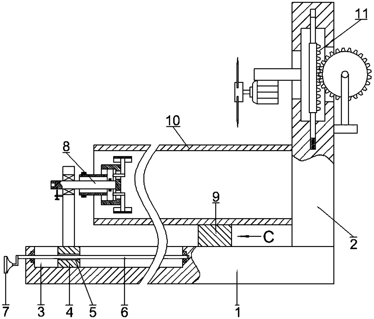
[0032] see figure 1 , in this embodiment, a cutting device for aluminum alloy pipes with clamping and rotating functions, including a base plate 1, a vertical plate 2 is fixedly connected to the upper side of the right end of the base plate 1, and a vertical plate 2 with an opening facing upwards is opened on the base plate 1 Moving groove 3, moving block 4 is arranged in moving groove 3, is provided with horizontal threaded through hole 5 on the moving block 4, and horizontal threaded through hole 5 internal thread is connected with horizontal threaded rod 6, and the two ends of horizontal threaded rod 6 and moving groove 3 The two ends are rotationally connected, and the outer end of the horizontal threaded rod 5 is fixedly connected with a handle 7, and...


PUM


Abstract

The invention provides a cutting device for an aluminum alloy tube with a clamping rotation function. The device comprises a bottom plate, a vertical plate is fixedly connected to the upper side of the right end of the bottom plate, a moving groove with an opening facing upward is formed in the bottom plate, the moving groove is internally provided with a moving block, a horizontal threaded through hole is formed in the moving block, the horizontal threaded through hole is internally in threaded connection with a horizontal threaded rod, the two ends of the horizontal threaded rod are rotatably connected with the two ends of the moving groove, the outer end of the horizontal threaded rod is fixedly connected a handle, a clamping rotation device is fixedly connected with the upper side of the moving block, and the outer side of the clamping rotation device is sleeved with the aluminum alloy tube; the upper side of the bottom plate is further provided with a supporting body. The device has the advantages that the moving block matched with the horizontal threaded rod moves to the right side in the moving groove, the right end of the aluminum alloy tube abuts the side wall of the vertical plate, each time lengths cut of the aluminum alloy tube are equal, it is not necessary to measure each time, and the cutting efficiency is effectively improved.

Description

technical field [0001] The invention relates to the technical field of aluminum alloy processing, in particular to an aluminum alloy pipe cutting device with a clamping and rotating function. Background technique [0002] Aluminum alloy is the most widely used non-ferrous metal structural material in industry, and has been widely used in aviation, aerospace, automobile, machinery manufacturing, shipbuilding and chemical industry. With the rapid development of industrial economy, the demand for welded structural parts of aluminum alloy is increasing day by day, so that the research on weldability of aluminum alloy is also in-depth. Aluminum alloy has low density, but relatively high strength, which is close to or exceeds high-quality steel. It has good plasticity and can be processed into various profiles. It has excellent electrical conductivity, thermal conductivity and corrosion resistance. It is widely used in industry, and its usage is second only to steel. . Some alum...

Claims


Application Information

Patent Timeline
Patent Type & Authority Applications(China)
IPC IPC(8): B23D21/00B23D33/02
CPCB23D21/00B23D33/02
Inventor 许媛
Owner 许媛
Why Eureka
Try Eureka