Automatic polishing numerical control device

A numerical control device and automatic polishing technology, applied in the direction of automatic grinding control device, grinding/polishing safety device, grinding/polishing equipment, etc., can solve the problem of reducing continuous production capacity, reducing production efficiency, production volume, and labor costs Advanced problems, to achieve the effect of improving continuous production capacity, increasing efficiency and production volume, and high degree of automation

Inactive Publication Date: 2018-11-23
芜湖遥帆电子科技有限公司
View PDF0 Cites 0 Cited by
  • Summary
  • Abstract
  • Description
  • Claims
  • Application Information

AI Technical Summary

Problems solved by technology

[0003] The current polishing device has a relatively complex structure and is inconvenient to operate; most of them require manual loading and unloading, the labor cost is high, and the degree of automation is not very high, which reduces the production efficiency and throughput; in addition, it is easy to produce A large amount of waste and dust, the existing ones are generally unable to be collected in time, which will easily cause the machine to stop for cleaning during the processing process, reducing its continuous production capacity; and the general throwing disc does not use permanent magnet materials, which reduces the fixing of the polishing disc and has a certain amount of noise

Method used


Image

  • Automatic polishing numerical control device
  • Automatic polishing numerical control device
  • Automatic polishing numerical control device

Examples


Embodiment 1

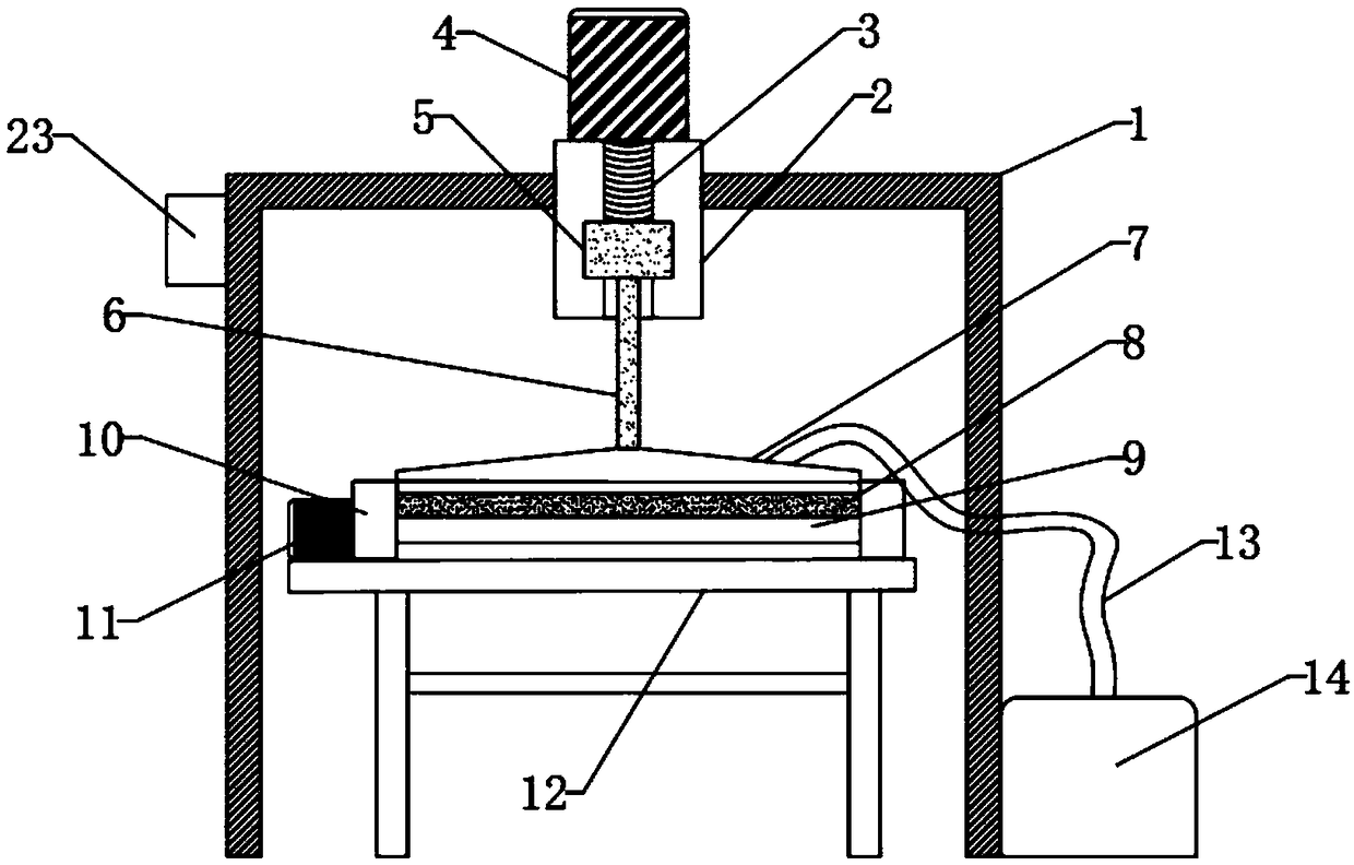
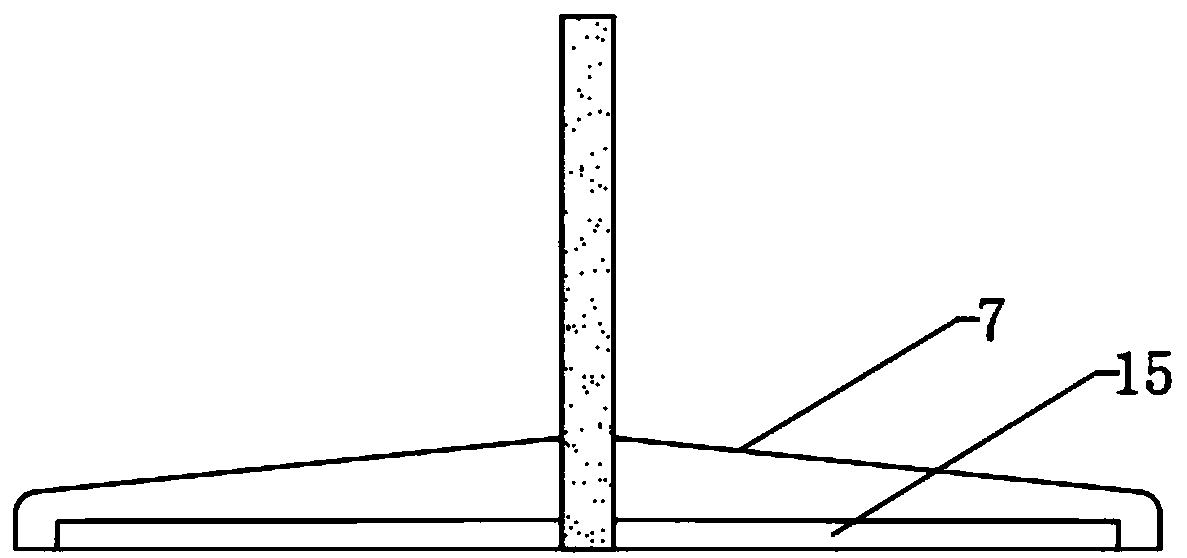
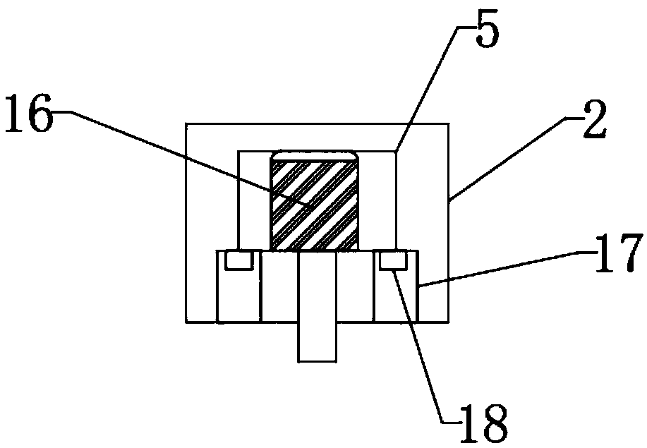
[0023] Such as Figure 1-6 As shown, the present invention provides a kind of automatic polishing numerical control device, comprises support frame 1, stepping motor 4, polishing cover 7, polishing plate 8, conveying motor 11, cyclone dust collector 14, polishing disk 15, polishing motor 16, A pressure sensor 18, a PLC controller 23, a fixed plate 2 is fixedly installed at the middle end of the top of the support frame 1, a stepper motor 4 is fixedly installed above the top of the fixed plate 2, a screw 3 is fixedly installed on the surface of the fixed plate 2, and a screw 3 is fixedly installed on the surface of the fixed plate 2. A slide block 5 is installed, and the middle end of the slide block 5 is fixedly equipped with a polishing motor 16, the bottom of the polishing motor 16 is fixedly connected with a push rod 6, the bottom end of the push rod 6 is fixedly connected with a polishing disc 15, and the top of the polishing disc 15 is fixedly equipped with a polishing dis...


PUM


Abstract

The invention discloses an automatic polishing numerical control device. The automatic polishing numerical control device comprises a stepping motor, a conveyer motor, a cyclone dust collector, a polishing disk, a polishing motor, a pressure sensor and a PLC (programmable logic controller), wherein the stepping motor is fixed above the top of a fixing plate, and the surface of the fixing plate isfixedly provided with a screw; the bottom of the polishing motor is fixedly connected with a push rod, the bottom end of the push rod is fixedly connected with a polishing disk, the top of the polishing disk is fixedly connected with a polishing cover, and the bottom of the polishing disk is provided with a plate to be polished; the bottom of the conveyer motor is fixedly provided with a bottom rack, and the polishing cover and the cyclone dust collector are connected through a dust collecting pipe; the internal top end of a limiting block is fixedly provided with the pressure sensor; the lefttop end of a support frame is fixedly provided with the PLC. The automatic polishing numerical control device is simple in structure, convenient to operate, high in automation degree and capable of achieving full automation and increasing the production efficiency and yield; by means of the cyclone dust collector, the automatic polishing numerical control device can rapidly and timely clean dustto provide a comfortable polishing environment and accordingly to improve the continuous production capacity.

Description

technical field [0001] The invention relates to a polishing device, in particular to an automatic polishing numerical control device. Background technique [0002] Polishing device is an electric tool. The polishing machine is composed of basic components such as a base, a throwing plate, a polishing fabric, a polishing cover, and a cover. It is specially used for effect treatment on the surface and pipes of metal products such as steel, aluminum, copper, etc. Dozens of original accessories meet the requirements. For different needs, it is easy to produce various snow patterns, brushed patterns, wave patterns, matte surfaces, mirror surfaces, etc. with different precision, quickly repair deep scratches and slight scratches, and quickly polish and polish. [0003] The current polishing device has a relatively complex structure and is inconvenient to operate; most of them require manual loading and unloading, the labor cost is high, and the degree of automation is not very hig...

Claims


Application Information

Patent Timeline
IPC IPC(8): B24B29/00B24B41/00B24B51/00B24B55/04B24B55/06
CPCB24B29/00B24B41/005B24B51/00B24B55/04B24B55/06
Inventor 邓海
Owner 芜湖遥帆电子科技有限公司
Why Eureka
Try Eureka