Earth pressure balance shield synchronous slurry injection structure and construction assistance system

An earth pressure balance shield and mud injection technology, which is used in earth-moving drilling, wellbore lining, tunnel lining, etc., can solve the problem that the gap between the shield excavation surface and the outer diameter of the segment is not fully filled, and the shield tunneling attitude is difficult to control. , the effect is not ideal and other problems, to achieve the effect of reducing the probability of wrapping the shield body, reducing the probability of surging, and reducing the amount of synchronous grouting

Pending Publication Date: 2018-11-23
POWERCHINA RAILWAY CONSTR +1
View PDF6 Cites 5 Cited by
  • Summary
  • Abstract
  • Description
  • Claims
  • Application Information

AI Technical Summary

Problems solved by technology

[0003] Affected by the existing earth pressure balance shield design and synchronous grouting equipment, there are the following deficiencies in the construction process of the earth pressure balance shield: First, the existing shield machine adopts the front large shield body to prevent the shield body from being stuck. Small rear design, the diameter of the shield excavation surface is about 30mm larger than the diameter of the front shield
Under the geological conditions of soft rock, the pressure of the soil tank and the synchronous grouting pressure of the shield tail cannot affect the middle of the shield body. As the shield machine advances, the soil above the shield body moves down to fill the gap between the excavation surface and the shield body , resulting in surface subsidence (refer to figure 1 ); secondly, under the condition that the excavation surface has a certain self-arching stratum, in order to prevent the shield cutter head and the soil tank from forming mud cakes, the shield machine generally adopts air pressure or semi-open excavation, and the synchronous grouting is in a flowing state. Inevitably flow along the shield body into the soil tank, resulting in a large loss of synchronous slurry
Especially in the downhill excavation section of shield tunneling, the amount of synchronous grout loss is greater (at this stage, the amount of synchronous grouting is required to be 1.2 to 1.8 times the theoretical amount), and the gap between the excavation surface of the shield tunneling surface and the outer diameter of the segment is not fully filled ( refer to figure 2 ), the current stage mainly uses secondary supplementary grouting at the positions behind the tail of the shield, but it is also difficult to ensure that the gaps are fully filled; the third is that the synchronous grout flows around the shield body, and a long stop time will cause the synchronous grout to wrap the shield body , leading to problems such as difficult control of the shield tunneling attitude; fourth, the filling of the gap between the excavation surface of the shield tunnel and the outer diameter of the segment is not full, and the seepage of the soil fills the gap and collects into the soil cabin through the shield body, thereby causing the shield tunneling to spew And other problems, although at this stage, cement and water glass double slurry are used to seal the water outside the entire segment at a certain distance behind the shield tail, but the effect is not ideal
[0004] The above four deficiencies in the construction process of the earth pressure balance shield are mainly due to the design of the shield and the characteristics of the synchronous slurry. There is a certain gap between the shield body and the excavation surface, which leads to problems such as surface settlement and loss of synchronous slurry.

Method used


Image

  • Earth pressure balance shield synchronous slurry injection structure and construction assistance system
  • Earth pressure balance shield synchronous slurry injection structure and construction assistance system
  • Earth pressure balance shield synchronous slurry injection structure and construction assistance system

Examples


Embodiment Construction

[0016] The present invention will be further described below in conjunction with the accompanying drawings and embodiments.

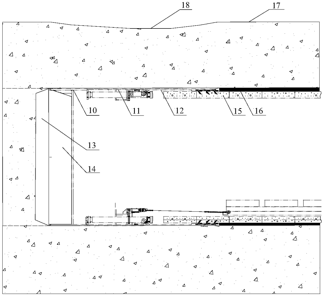
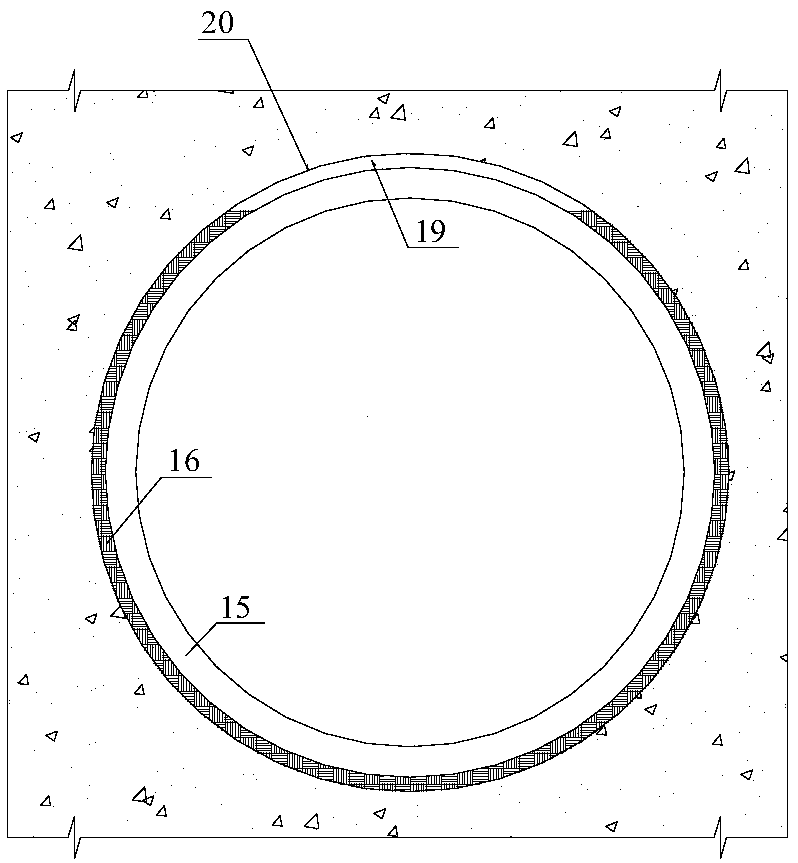
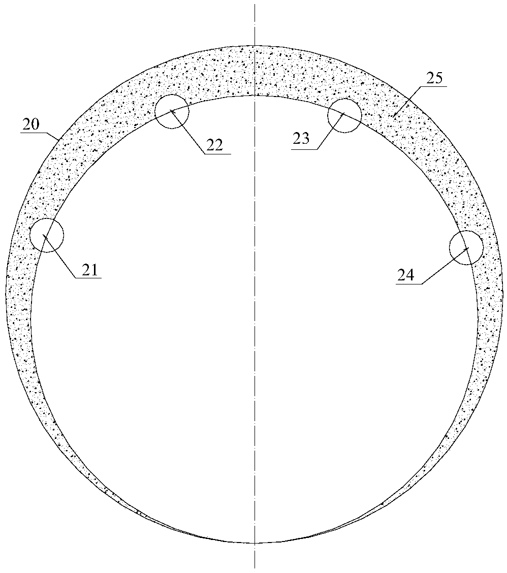
[0017] refer to figure 1 , a synchronous mud injection structure of an earth pressure balance shield of the present invention, the shield body includes a cutter head 13, a soil cabin 14, a front shield 10, a middle shield 11, a shield tail 12, and a segment behind the shield tail 12 The synchronous grouting in the gap between 15 and the shield excavation surface 20 forms the synchronous grouting filling layer 16 . refer to image 3 and Figure 4 , the middle shield 11 is provided with circumferentially spaced mud injection ports, through which plastic mud is injected into the space outside the shield between the shield body and the tunnel excavation surface 20, and the plastic mud is injected into the front shield 10 and shield tail 11 The space outside the shield diffuses, and the space outside the shield is densely filled to form a plastic mud fill...


PUM


Abstract

The invention relates to an earth pressure balance shield synchronous slurry injection structure and a construction assistance system. The earth pressure balance shield synchronous slurry injection structure and a construction assistance system is characterized in that a shield body comprises a cutter head, an earth cabin, a front shield, a middle shield and a shield tail, and a synchronous-injection filling layer is formed in a gap between a segment at the rear of the shield tail and a shield excavation face; the middle shield is provided with slurry injection ports which are annularly arranged at intervals, plastic slurry is injected into the gap, between the shield body and a tunnel excavation face, outside the shield, the plastic slurry diffuses towards the gaps, outside the shield, ofthe front shield and the shield tail and densely fill the gaps outside the shield to form the plastic slurry filling layer, and the synchronous-injection slurry is prevented from flowing into the earth cabin. By the earth pressure balance shield synchronous slurry injection structure and the construction assistance system, the synchronous-injection slurry can be prevented from running off into the earth cabin through the outer side of the shield body, synchronous slurry injection quantity is lowered greatly, and accordingly construction cost is lowered.

Description

technical field [0001] The invention relates to shield tunnel construction, in particular to an earth pressure balance shield synchronous mud injection structure and a construction auxiliary system. Background technique [0002] During the construction of the earth pressure balance shield, as the soil in front of the excavation of the cutter head of the shield machine is excavated forward, the shield moves with the shield machine, and a certain gap is formed between the outer surface of the segment and the excavation surface. The design of shield adopts synchronous grouting to fill full every time to ensure the stability of the excavation surface and control the settlement of the ground surface. The synchronous slurry is generally composed of cement, fly ash, bentonite, sand, water, admixtures and other materials. Due to the limitation of equipment and pipelines, the synchronous slurry is in a flowing state. Generally, the initial setting time is 6 hours and the final settin...

Claims


Application Information

Patent Timeline
Patent Type & Authority Applications(China)
IPC IPC(8): E21D9/08E21D11/10E21D9/00
CPCE21D9/001E21D9/08E21D11/10
Inventor 王国义蒋宗全孟庆明李宁
Owner POWERCHINA RAILWAY CONSTR
Why Eureka
Try Eureka