
Relaxation oscillator

A relaxation oscillator and oscillation unit technology, applied in the direction of electric pulse generator circuit, differential amplifier to generate pulse, pulse generation, etc., can solve the problems of actual frequency and theoretical frequency deviation, chip capacitance value error, chip current power consumption increase, etc. , to achieve the effects of reduced circuit power consumption, fast comparator speed, and reduced total current

Pending Publication Date: 2018-11-23
HANGZHOU HONGXIN MICROELECTRONICS TECH CO LTD
View PDF5 Cites 7 Cited by
  • Summary
  • Abstract
  • Description
  • Claims
  • Application Information

AI Technical Summary

Problems solved by technology

If we want to generate a high-frequency signal, we need a smaller capacitor or a larger current, but a smaller capacitor will cause an error in the actual on-chip capacitor value, resulting in a large deviation between the actual frequency and the theoretical frequency
But if the current is increased, the actual chip current consumption will increase

Method used


Image

  • Relaxation oscillator
  • Relaxation oscillator
  • Relaxation oscillator

Examples


Embodiment Construction

[0033] The above and other technical features and advantages of the present invention will be clearly and completely described below in conjunction with the accompanying drawings. Apparently, the described embodiments are only some of the embodiments of the present invention, not all of them.

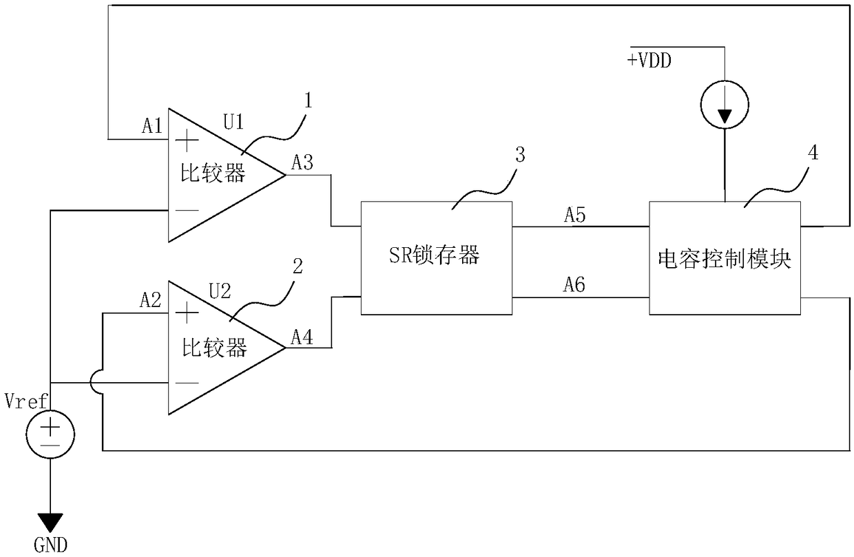
[0034] Such as figure 1 As shown, a relaxation oscillator includes a first comparator 1, a second comparator 2, an SR latch 3, and a capacitance control module 4. By making the first comparator 1 generate a first comparison according to an external reference reference threshold voltage The signal and the second comparison signal generated by the second comparator 2 are input to the SR latch 3 to generate a control signal, and the first capacitor C1 and the first capacitor C1 are controlled according to the bias current of the external bias current source and the control signal output by the SR latch 3 The periodic charging and discharging of the second capacitor C2 generates an oscillat...


PUM


Abstract

The invention provides a relaxation oscillator, comprising a first comparator, a second comparator, an SR latch and a capacitor control module. An input terminal of the first comparator is coupled with a capacitor control module and an external reference threshold voltage, and an output terminal of the first comparator is coupled with an input terminal of the SR latch. An input terminal of the second comparator is coupled with the capacitor control module and the external reference threshold voltage, and an output terminal of the second comparator is coupled with the input terminal of the SR latch. An output terminal of the SR latch is coupled with an input terminal of the capacitor control module. A bias current input terminal of the capacitor control module is coupled to an external biascurrent source. A control signal is generated by inputting a first comparison signal generated by the first comparator and a second comparison signal generated by the second comparator into the SR latch according to the external reference threshold voltage, and a first capacitor and a second capacitor are controlled to periodically charge and discharge to generate an oscillation signal accordingto a bias current of the external bias current source and the control signal output from the SR latch.

Description

technical field [0001] The invention relates to the technical field of oscillators, in particular to a relaxation oscillator. Background technique [0002] A relaxation oscillator is a nonlinear electronic oscillator circuit capable of generating a repetitive output signal of a triangular or square wave. The circuit consists of a feedback loop, usually a switching device such as a transistor, comparator, relay, operational amplifier, and active device inductor or capacitor. [0003] It repeatedly charges the capacitor with current until it reaches a threshold level, and then discharges it again. The period of the oscillator depends on the time constant of this capacitive circuit. Capacitors switch abruptly between charge and discharge modes, creating repetitive waveforms that vary discontinuously. This scheme is usually used to generate low frequency signals. If we want to generate a high-frequency signal, we need a smaller capacitor or a larger current, but a smaller ca...

Claims


Application Information

Patent Timeline
Patent Type & Authority Applications(China)
IPC IPC(8): H03K3/011H03K3/023
CPCH03K3/011H03K3/023H03K3/0231
Inventor 邹何洪何一超李晴平
Owner HANGZHOU HONGXIN MICROELECTRONICS TECH CO LTD
Learn More