Improved broadband microstrip antenna unit

A microstrip antenna and broadband technology, applied in the direction of the antenna, the antenna grounding device, the structure connection of the antenna grounding switch, etc. The effect of small backward radiation, stable gain and widening antenna bandwidth

Inactive Publication Date: 2018-12-04
XIDIAN UNIV
View PDF3 Cites 24 Cited by
  • Summary
  • Abstract
  • Description
  • Claims
  • Application Information

AI Technical Summary

Problems solved by technology

Although these methods can broaden the antenna bandwidth, they may cause the deterioration of the antenna radiation pattern and cause some problems for feeding
[0004] In the paper "Wide-Bandwidth 60-GHz Aperture-Coupled Microstrip Patch Antennas (MPAs) Fed by Substrate Integrated Waveguide (SIW)" published by Wael M. Abdel-Wahab, a substrate-integrated waveguid

Method used


Image

  • Improved broadband microstrip antenna unit
  • Improved broadband microstrip antenna unit
  • Improved broadband microstrip antenna unit

Examples


Embodiment 1

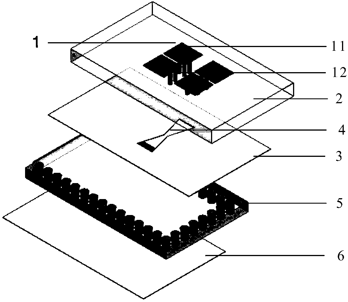
[0024] refer to figure 1 , this example includes a radiator 1, a dielectric substrate 2, an upper floor 3, a feed structure 5, and a lower floor 6. The upper floor 3 is connected between the dielectric substrate 2 and the feed structure 5 by pressing, and the lower floor 6 is located at The lower surface of the feed structure 5 and the upper floor 3 are etched with transverse slits 4 for coupling energy from the feed structure 5 to the radiator 1; the radiator 1 includes electric dipoles 11 and magnetic dipoles 12, The electric dipole 11 and the magnetic dipole 12 are placed perpendicularly to each other, and the electric dipole 11 is located on the upper surface of the dielectric substrate 2; Connected, the lower surface is connected with the lower floor 3.

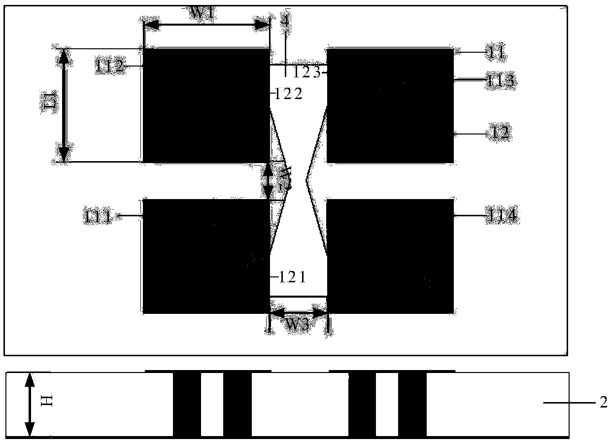
[0025] refer to figure 2 , the electric dipole 11 is composed of N pairs of rectangular patches arranged on both sides of the transverse symmetry axis of the transverse gap 4, and the magnetic dipole 12 is composed of...

Embodiment 2

[0044] Embodiment 2, the structure of this embodiment is identical with the structure of embodiment 1, and following parameter has been adjusted:

[0045] The length L1 of the rectangular patch = 1.1mm, the width W1 = 1.1mm; the distance between the first rectangular patch 111 and the second rectangular patch 112 is W2 = 0.2mm, the first rectangular patch 111 and the third rectangular patch 113 The distance W3=0.5mm; the diameter of the metal hole is d=0.2mm, the height is H=0.762mm, and the side length P=0.45mm of the right-angled side of the isosceles right-angled triangle formed; The distances between the wide side and the long side of the patch 111 are respectively: W4=0.2mm, W5=0.22mm.

Embodiment 3

[0046] Embodiment 3, the structure of this embodiment is the same as that of Embodiment 1, and the following parameters have been adjusted:

[0047] The length L1 of the rectangular patch = 2.2mm, the width W1 = 3.5mm; the distance between the first rectangular patch 111 and the second rectangular patch 112 is W2 = 1.0mm, the first rectangular patch 111 and the third rectangular patch 113 The distance W3=1.4mm; the diameter of the metal hole is d=0.4mm, the height is H=1.27mm, and the side length P=1mm of the right angle side of the isosceles right triangle formed; the center of the metal hole at the apex of the right angle is attached to the first rectangle The distances between the wide side and the long side of the sheet 111 are respectively: W4=0.4mm, W5=0.7mm.

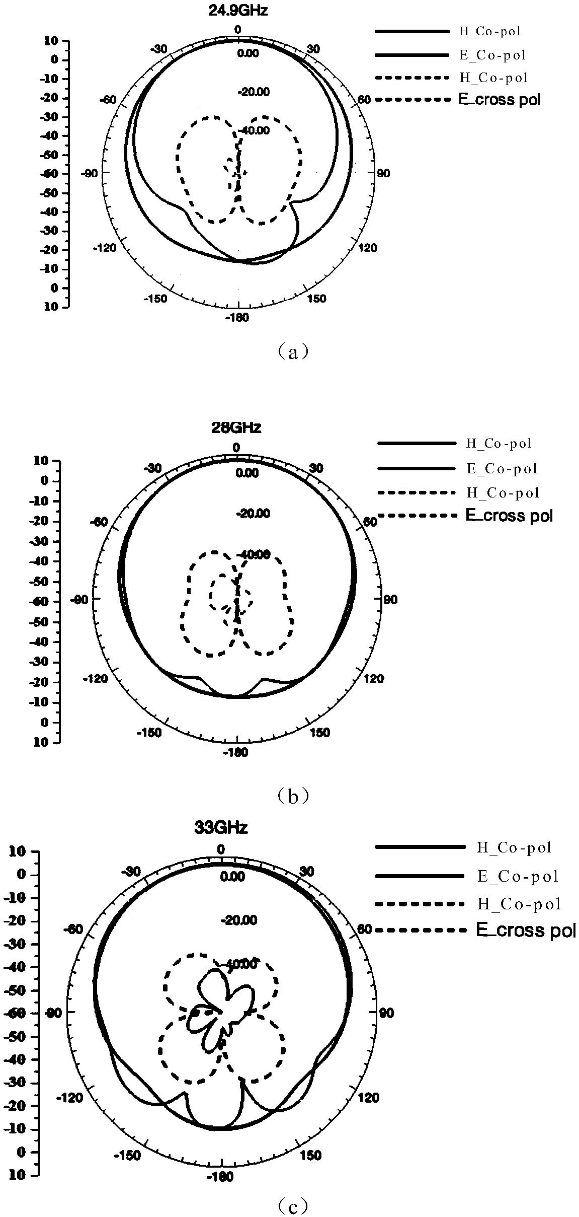
[0048] Effect of the present invention can be illustrated by following simulation:

[0049] 1. Simulation software: commercial simulation software HFSS_15.0.

[0050] 2. Simulation content:

[0051] Simulation ...


PUM

PropertyMeasurementUnit
Lengthaaaaaaaaaa
Widthaaaaaaaaaa
Diameteraaaaaaaaaa

Abstract

The invention discloses an improved broadband microstrip antenna unit, which mainly solves the problems of narrow band width, high cross polarization and backward radiation of conventional microstripantennas. The antenna of the invention comprises a radiator (1), a dielectric substrate (2), an upper floor plate (3), a feed structure (5) and a lower floor plate (6). The upper floor plate is positioned between the dielectric substrate and the feed structure, and the lower floor plate is located on the lower surface of the feed structure. The upper floor plate is provided with a transverse gap (4) through etching. The radiator comprises an electric dipole (11) and a magnetic dipole (12). The electric dipole is composed of N pairs of rectangular patches arranged on both sides of the transverse symmetry axis of the transverse gap and horizontally arranged on the upper surface of the dielectric substrate. The magnetic dipole is composed of M metal connectors inside the dielectric substrate.The electric dipole is connected with the upper floor plate through the magnetic dipole, and the magnetic dipole and the electric dipole are arranged perpendicular to each other. The improved broadband microstrip antenna unit is improved in working bandwidth, is reduced in cross polarization and backward radiation, and can be applied to 5G communication and radar systems.

Description

technical field [0001] The invention belongs to the technical field of antennas, and further relates to an improved broadband microstrip antenna unit, which can be used in 5G communication and radar systems. Background technique [0002] With the rapid development of 5G communication, the 5G communication system puts forward higher and higher requirements on the bandwidth of the antenna. Microstrip antennas are widely used in wireless communication and radar systems due to their advantages of small size, light weight, low profile, easy integration and low manufacturing cost. [0003] Due to the high quality factor of the traditional microstrip antenna, the expansion of its frequency band is limited, and the antenna bandwidth can only reach about 1%-5%, and the impedance bandwidth is small, which limits the practical application range of the microstrip antenna. At this stage, the 5G communication frequency band is developing towards millimeter waves, requiring antennas with ...

Claims


Application Information

Patent Timeline
IPC IPC(8): H01Q1/36H01Q1/38H01Q1/48H01Q1/50H01Q13/08
CPCH01Q1/36H01Q1/38H01Q1/48H01Q1/50H01Q13/08
Inventor 李龙李美灵易浩
Owner XIDIAN UNIV
Why Eureka
Try Eureka