Double-ended output linear cavity all-fiber laser oscillator

A laser oscillator, double-end output technology, applied in lasers, laser parts, phonon exciters, etc., can solve the problem that lasers are difficult to withstand high-power output, cannot use high-power fiber combiners, and limit pump laser injection. Power and other issues, to achieve the effect of reducing power density, ensuring stability, and stable and reliable transmission

Pending Publication Date: 2018-12-07
BWT BEIJING
View PDF21 Cites 6 Cited by
  • Summary
  • Abstract
  • Description
  • Claims
  • Application Information

AI Technical Summary

Problems solved by technology

In this structure, since the core of the passive energy transfer fiber does not overlap with the core of the active doped fiber, in order to realize pump injection and signal laser transmission respectively, the two need to be separated in structure. The cladding will inevitably be damaged to a certain extent, making it difficult for this type of laser to withstand high power output above 1 kW
In addition, in this structure, since the core of the passive energy-transfer fiber and the core of the active doped fiber have different axes, a high-power fiber combiner based on double-clad fiber cannot be used, which limits the injection power of the pump laser.
[0005] Among the existing two-way output lasers, one class uses spatially structured optical mirrors and lenses to realize laser reflection and coupling, and its stability is poor due to the need for fine adjustment of the mirrors; the other class uses a dual-core optical fiber structure, pumping Low injection power and limited output laser power

Method used


Image

  • Double-ended output linear cavity all-fiber laser oscillator
  • Double-ended output linear cavity all-fiber laser oscillator
  • Double-ended output linear cavity all-fiber laser oscillator

Examples


Embodiment 1

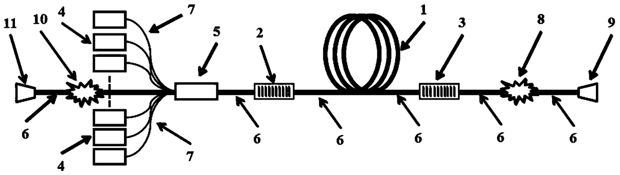
[0029] A linear cavity all-fiber laser oscillator with double-ended output, the structure diagram is as follows figure 1 As shown, it includes gain fiber 1, backward fiber grating 2, forward fiber grating 3, fiber-coupled semiconductor laser 4, pump signal beam combiner 5, signal energy transmission fiber 6, pump energy transmission fiber 7, forward Cladding light filter 8, forward output fiber end cap 9, backward cladding light filter 10, backward output fiber end cap 11; backward fiber Bragg grating 2, gain fiber 1, and forward fiber Bragg grating 3 pass through The signal energy transmission optical fiber 6 is sequentially connected to form a fiber laser resonator; the backward fiber grating 2, the gain fiber 1, and the forward fiber grating 3 are connected sequentially through the signal energy transmission optical fiber 6 to form a fiber laser resonator; the signal energy transmission optical fiber 6 will The forward fiber grating 3, the forward cladding optical filter 8 ...

Embodiment 2

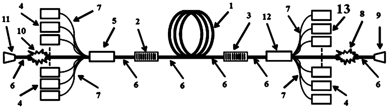
[0038] A double-ended pumping, double-ended output linear cavity all-fiber laser oscillator, its structure schematic diagram is as follows figure 2 shown. On the basis of Embodiment 1, a second pump signal combiner 12 and a corresponding second fiber-coupled semiconductor laser 13 are added to form a double-end pumped fiber laser oscillator, and the pump power injected into the resonator is increased. The second pump signal combiner 12 is arranged between the forward fiber grating 3 and the forward cladding optical filter 8; the second pump signal combiner 12 includes a signal input arm, a signal output arm, a or a plurality of pump input arms; the signal output arm of the second pump signal combiner 12 is connected to the forward fiber grating 3 through the signal energy transmission fiber 6, and its signal input arm is connected to the forward layer optical filter 8 through the signal The energy transmission fiber 6 is connected, and its pump input arm is connected to the ...

Embodiment 3

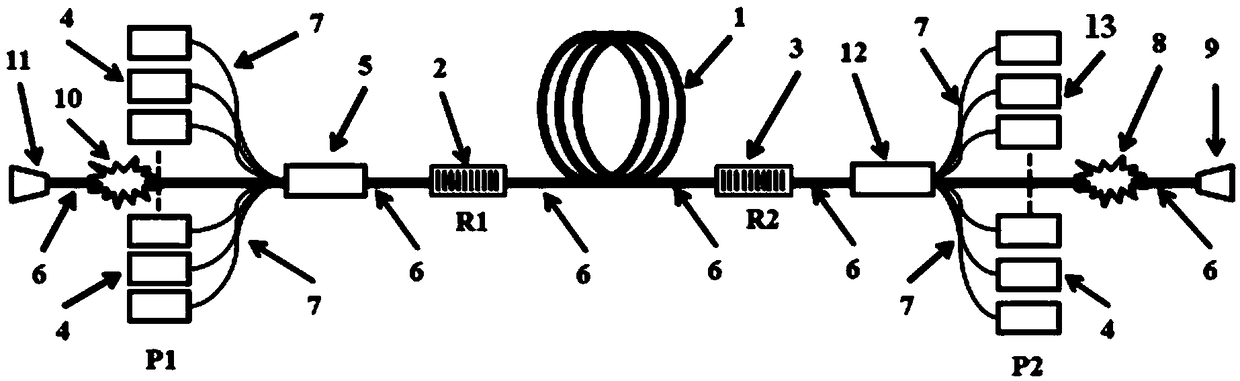
[0041] A linear cavity all-fiber laser oscillator with the same output power at both ends, its schematic structure is as follows image 3 shown. On the basis of embodiment 2, the backward fiber grating and the forward fiber grating are selected as fiber gratings with equal reflectivity, that is, the reflectivity R1 of the forward output reflection grating 3 is equal to the reflectivity R2 of the backward output grating 2; and , the total power of the fiber-coupled semiconductor laser 4 injected into the forward pump signal combiner 5 is equal to the total power of the second fiber-coupled semiconductor laser 13 injected into the backward pump signal combiner 12, that is, the fiber-coupled semiconductor laser 4 The total power P1 injected into the pump signal combiner 5 and the total power P2 injected into the second pump signal combiner 12 are equal to ensure that the output power at both ends of the oscillator is equal. The structural diagram is as follows image 3 shown.

...


PUM


Abstract

The invention provides a double-ended output linear cavity all-fiber laser oscillator comprising a gain fiber, a backward output fiber grating, a forward output fiber grating, a fiber coupled semiconductor laser, a pump signal combiner, a signal energy transmission fiber, a pump energy transmission fiber, a forward cladding optical filter, a forward output fiber end cap, a backward cladding optical filter and a backward output fiber end cap. The backward output fiber grating, the gain fiber and the forward output fiber grating are connected in turn to form a fiber laser resonant cavity throughthe signal energy transmission fiber. The fiber coupled semiconductor laser outputs pump light to be injected into the pump signal beam combiner through the pump energy transmission fiber and then injected into the fiber laser resonant cavity through the signal energy transmission fiber. The reflectivity of forward and backward fiber gratings is not greater than 95% so that the laser generated bythe resonant cavity can be outputted from both ends of the resonant cavity. The laser outputted from both ends of the fiber laser resonant cavity passes through the forward and backward cladding optical filters and then is outputted by the connected fiber end cap after beam expansion.

Description

technical field [0001] The present invention generally relates to the field of fiber lasers, in particular to a double-end output linear cavity all-fiber laser oscillator. Background technique [0002] Fiber lasers generally include two types of laser oscillators based on single resonator and laser amplifiers based on the main oscillation power amplification structure. Compared with the main oscillation power amplification structure fiber amplifier, the all-fiber laser oscillator has the advantages of low cost, compact structure, simple control logic, stable performance, strong anti-reflection ability, etc., and has a wide range of applications in industrial processing. With the expansion of application fields, all walks of life have higher and higher requirements for laser cost control. At present, in order to ensure the effective start-up of the high-power fiber laser used in the industry, a resonant cavity composed of a high-reflection grating and a low-reflection gratin...

Claims


Application Information

Patent Timeline
Patent Type & Authority Applications(China)
IPC IPC(8): H01S3/067H01S3/094
CPCH01S3/06716H01S3/06733H01S3/0675H01S3/06783H01S3/094042
Inventor 王小林叶云奚小明史尘张汉伟韩凯王泽锋许晓军周朴司磊陈金宝
Owner BWT BEIJING
Why Eureka
Try Eureka