Multifunctional coherent raman scattering biological imaging light source

A technology of Raman scattering and biological imaging, which is applied in the direction of laser scattering effect, laser, laser parts, etc., can solve the problems of insufficient detection sensitivity, low pump light utilization rate, and inaccurate information, etc., to reduce costs, The effect of improving parameter conversion efficiency and improving resolution

Active Publication Date: 2018-12-07
UNIV OF SHANGHAI FOR SCI & TECH
View PDF4 Cites 12 Cited by
  • Summary
  • Abstract
  • Description
  • Claims
  • Application Information

AI Technical Summary

Problems solved by technology

[0004] Traditional CARS imaging technology and SRS imaging technology are designed as a single-cavity parametric oscillation structure due to different requirements for light sources, and the pump light in the single-cavity cavity is lost because it cannot participate in feedback and four-wave mixing occurs, making the system The pump light utilization rate is not high
Moreover, although a single CARS or SRS imaging light source technology has its own advantages, it also has its shortcomings. The information obtained is not accurate enough, and the detection sensitivity is not high enough.
Therefore, in order to obtain accurate and rich sample images, it is often necessary to use multiple imaging methods comprehensively, but the current light source cannot meet this requirement

Method used


Image

  • Multifunctional coherent raman scattering biological imaging light source
  • Multifunctional coherent raman scattering biological imaging light source
  • Multifunctional coherent raman scattering biological imaging light source

Examples


Embodiment 1

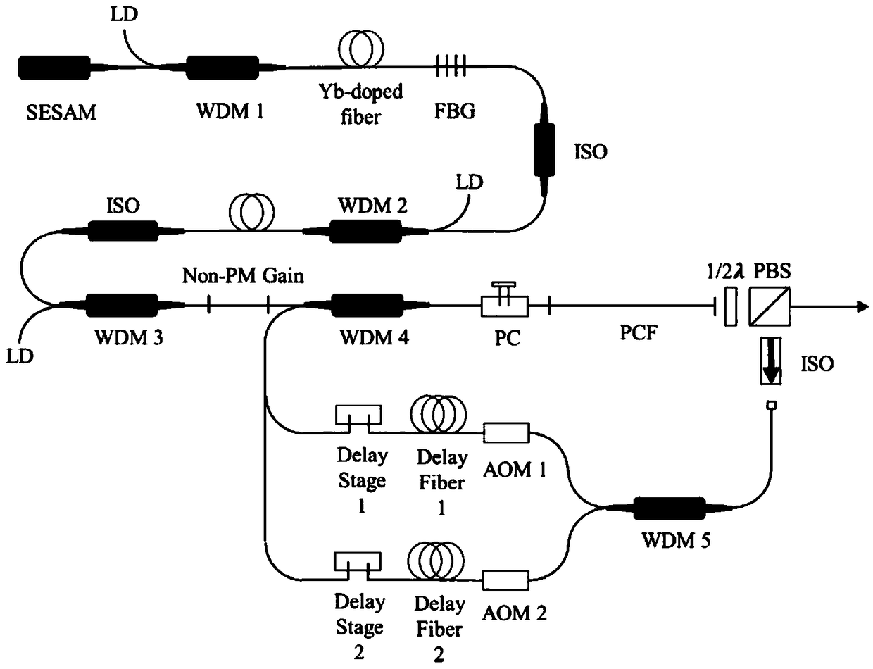
[0022] Embodiment one, figure 2 It is a structural diagram of the present embodiment, and its specific implementation process is as follows:

[0023] The oscillator of the biological imaging light source of the invention adopts the semiconductor saturable absorbing mirror SESAM passive mode-locking mode, and the cavity components include sequentially connected SESAM, wavelength division multiplexer WDM 1, ytterbium-doped Yb-doped gain fiber, and fiber Bragg grating FBG. The pulse seed light output by the oscillator is coupled to the Yb-doped gain fiber through the wavelength division multiplexer WDM 2 to amplify the average power of the seed light, and the isolator ISO is used to separate the two-stage amplification modules to prevent the return light from damaging the cavity Component; after that, the seed light is coupled to the secondary amplification module composed of non-polarization-maintaining Non-PM gain fiber through the wavelength division multiplexer WDM3 to reali...

Embodiment 2

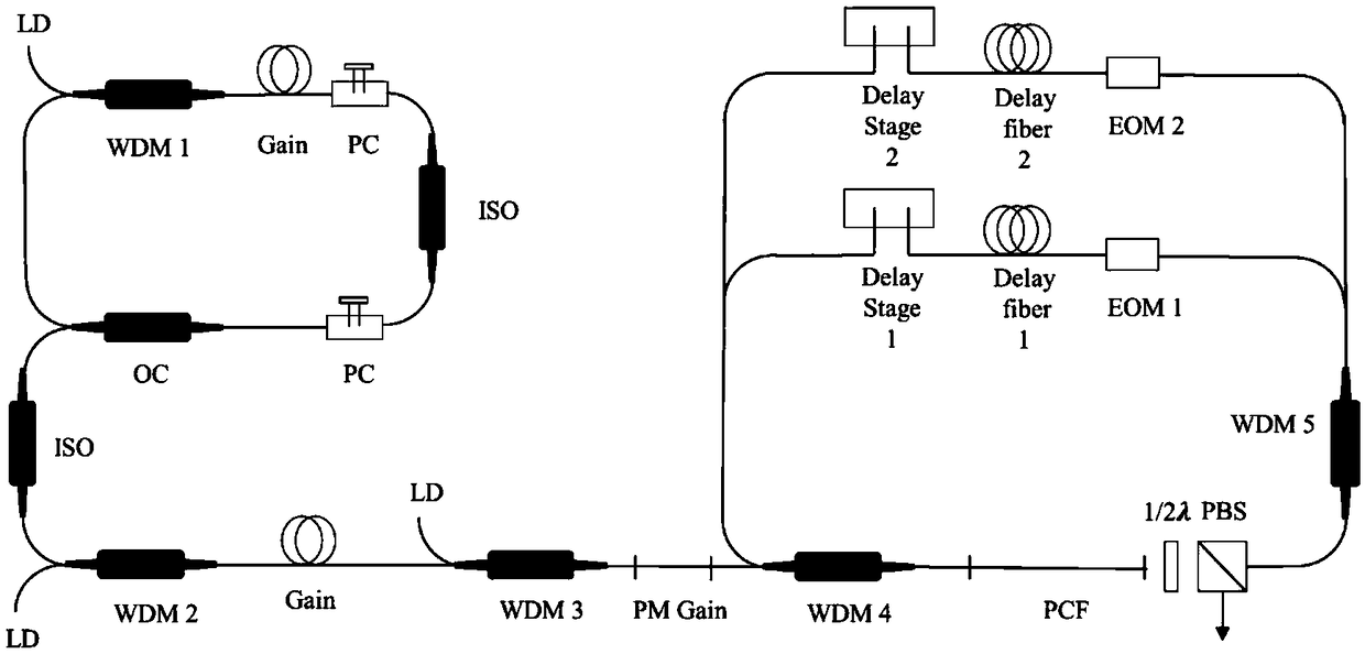
[0024] Embodiment two, image 3 It is the second structure diagram of this embodiment, and its specific implementation process is as follows:

[0025] The oscillator of the bio-imaging light source of the invention adopts nonlinear polarization rotation (NPR) passive mode-locking mode, and the cavity components include wavelength division multiplexer WDM 1, gain Gain fiber, polarization controller PC, isolator ISO, output Coupler OC. The oscillator outputs the pulsed seed light from the output coupler OC to increase the average power of the first-stage amplifier module, and the ISO separates the two-stage amplifier modules to prevent the returning light from damaging the cavity components; the output light of the first-stage large module enters the polarization-maintaining PM The secondary amplification module composed of gain fiber realizes the re-amplification of the seed light power to meet the threshold condition of parameter conversion; after that, through WDM 4, the coupl...

Embodiment 3

[0026] Embodiment three, Figure 4 It is the structure diagram of the third embodiment, and its specific implementation process is as follows:

[0027] The nonlinear biological imaging light source oscillator of the invention adopts the passive mode-locking mode of the nonlinear magnifying loop mirror (NALM). The cavity components include: WDM, band-pass filter BP, output coupler OC, isolator ISO, Gain, dispersion compensation fiber ( DCF). The pulsed seed light output by the oscillator enters the primary amplification module, and the average power of the seed light is increased. After that, the seed light enters the secondary amplification module composed of double-clad polarization-maintaining gain fiber (20 / 130) through the focusing lens. After the gain fiber Place a dichroic mirror DM1 with high transparency of 980 nm and high reflection pump light, and the continuous light of 980 nm is input from the reverse direction to realize the re-amplification of the seed light pow...


PUM


Abstract

The invention relates to a multifunctional coherent raman scattering biological imaging light source. Seed light output by a laser oscillator passes through primary and secondary amplification modules, so average power is improved, and a threshold value condition of parametric conversion is met. Amplified light enters a parametric conversion module through an optical coupler, so stokes light is generated and then is subjected to beam splitting through a power beam splitter. One part of the light is used as an imaging light source to be output and the other part enters a wavelength beam splitter, so separation of the stokes light and pump light is achieved. Separated light enters two repeated-frequency tuning modules which are capable of mutually independently controlling repeated frequencyof the stokes light and the pump light and are connected with a first-time time delay module and a second-time time delay module. Chromatic dispersion is adjusted, so two beams of feedback light passes the optical coupler and then is coupled to the parametric conversion module. Pump light and stokes light fed back to the optical coupler synchronize in time and coincide in space, so double parametric oscillation feedback is achieved. Thus, the high-efficiency multifunctional coherent raman scattering biological imaging light source is achieved.

Description

technical field [0001] The invention relates to an imaging light source device, in particular to a multifunctional coherent Raman scattering biological imaging light source. Background technique [0002] Coherent Raman scattering (CherentRaman Scattering, CRS) imaging technology is widely used in the fields of biology and medicine due to its label-free, non-invasive, non-damaging and chemical-specific characteristics. It uses two optical signals to resonate with the chemical bonds of the sample. , producing a beam characterizing the type of chemical bond. CRS imaging technology includes two imaging methods, Coherent Anti-Stokes Raman Scattering (CARS) and Stimulated Raman Scattering (SRS). The nonlinear effect of CARS and SRS enables CRS imaging technology to have good detection sensitivity and three-dimensional imaging capability, which can not only be used for molecular imaging that is difficult to label, but also avoid the phototoxicity of biological samples caused by th...

Claims


Application Information

Patent Timeline
Patent Type & Authority Applications(China)
IPC IPC(8): H01S3/30
CPCH01S3/302
Inventor 沈悦杨康文吴昱兴钟钰翠郝强曾和平
Owner UNIV OF SHANGHAI FOR SCI & TECH
Why Eureka
Try Eureka