Impedance match-type optical power control circuit of semiconductor laser pain therapy instrument

A technology of optical power control and impedance matching, applied in the field of medical equipment, can solve problems such as laser power attenuation, laser power instability, instability, etc.

Active Publication Date: 2018-12-11
河南省宇安医疗科技开发有限公司
View PDF6 Cites 1 Cited by
  • Summary
  • Abstract
  • Description
  • Claims
  • Application Information

AI Technical Summary

Problems solved by technology

[0002] Laser can produce biostimulation effect, promote cell regeneration, improve blood circulation, reduce inflammation and pain, reduce edema, regulate immune function of the body, semiconductor laser pain therapy device, adopts the wavelength range of 650/808nm human optical window, dual-wavelength composite light, tissue Penetration deepens up to 175px, produces multiple light effects, no trauma, no pain, safe and reliable, high output power, short treatment time, such as in ortho

Method used


Image

  • Impedance match-type optical power control circuit of semiconductor laser pain therapy instrument
  • Impedance match-type optical power control circuit of semiconductor laser pain therapy instrument

Examples


Embodiment 1

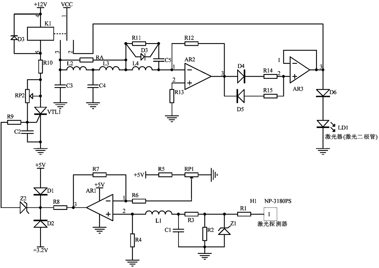
[0013] Embodiment 1, the impedance matching optical power control circuit of the semiconductor laser pain treatment instrument, the optical power signal acquisition circuit receives the laser power signal sent by the semiconductor laser pain treatment instrument laser LD1 through the laser detector of the model NP-3180PS, and the output is proportional to The 4-20mA current signal of the optical power of the laser is converted into a voltage signal by the current / voltage conversion circuit composed of resistor R1, voltage regulator Z1, and resistor R2. After that, the voltage signal is obtained by the subtractor with the operational amplifier AR1 as the core and proportional to the voltage difference. Amplify, the clamping circuit composed of diode D1 and diode D2 clamps +3.2V~+5V, the voltage regulator tube outputs after voltage stabilization, and the voltage difference signal after clamping and voltage stabilization is the trigger signal for triggering the thyristor VTL1 in th...

Embodiment 2

[0015] Embodiment 2. On the basis of Embodiment 1, the amplifying isolation circuit amplifies the ratio of the input power supply voltage VCC through a proportional amplifying circuit composed of an operational amplifier AR2, a resistor R12, and a resistor R13, wherein the ratio amplification factor is determined by the operational amplifier The input resistance of the inverting input terminal of AR2 is determined. The increase / decrease of the resistance value of the input resistance causes the magnification factor of the operational amplifier AR2 to decrease / increase, and the output signal of the amplifying isolation circuit decreases / increases, and finally passes through two diodes D3, D4 anti-parallel limiter and operational amplifier AR3 buffer isolation, through the diode D6 to provide a stable voltage for the laser LD1, including the operational amplifier AR2, the inverting input terminal of the operational amplifier AR2 is connected to trigger the resistance value output ...


PUM


Abstract

The invention discloses an impedance match-type optical power control circuit of a semiconductor laser pain therapy instrument, which comprises an optical power signal acquisition circuit, a trigger impedance conversion circuit and an amplification isolation circuit. The optical power signal acquisition circuit acquires laser power signals emitted by a laser, subtraction by an operational amplifier is carried out, voltage difference information is outputted, and trigger signals of a thyristor in the trigger impedance conversion circuit are triggered; when the voltage difference signals after clamping voltage stabilization are higher than 3.5 V, the resistance of the impedance conversion circuit formed by inductors L2 and L3 and capacitors C3 and C4 is increased, the impedance conversion circuit is then parallelly connected with a resistor RA and is then serially connected onto a resonant circuit formed by an inductor L4, a capacitor C5, a resistor R11 and a diode D3 for further impedance match, determined resistance is acquired and outputted as input resistor of an inverting input end of an operational amplifier AR2 in the amplification isolation circuit, after proportional amplification/buffer isolation, stable boosted power supply voltage VCC is provided for the laser, the power of light emitted by the laser LD1 is ensured to be constant, and therapy effects are achieved.

Description

technical field [0001] The invention relates to the technical field of medical devices, in particular to an impedance matching optical power control circuit of a semiconductor laser pain treatment instrument. Background technique [0002] Laser can produce biostimulation effect, promote cell regeneration, improve blood circulation, reduce inflammation and pain, reduce edema, regulate immune function of the body, semiconductor laser pain therapy device, adopts the wavelength range of 650 / 808nm human optical window, dual-wavelength composite light, tissue Penetration deepens up to 175px, produces multiple light effects, no trauma, no pain, safe and reliable, high output power, short treatment time, such as in orthopedics, bone pain, muscle pain, soft tissue pain, neuralgia, incision and wound pain, etc. It is widely used in trauma surgery and physical therapy of pain diseases. In actual use, due to the instability of the power supply voltage and the characteristics of the lase...

Claims


Application Information

Patent Timeline
IPC IPC(8): A61N5/067
CPCA61N5/06A61N5/067
Inventor 王天玉郭彦伟赵幸娟刘健江广生
Owner 河南省宇安医疗科技开发有限公司
Why Eureka
Try Eureka