High-temperature flue gas dust removal and denitration integrated device and process thereof

A technology of high-temperature flue gas and high-temperature dust collector, applied in chemical instruments and methods, dispersed particle separation, dispersed particle filtration, etc., can solve the problem that the utilization rate of ceramic tubes is not fully utilized, it is difficult to increase the length, and the ceramic through-hole ratio is low. and other problems, to achieve the effects of high mechanical strength, long service life and adjustable filter area

Inactive Publication Date: 2018-12-11
ZHEJIANG ZHENENG CATALYST TECH CO LTD
View PDF6 Cites 7 Cited by
  • Summary
  • Abstract
  • Description
  • Claims
  • Application Information

AI Technical Summary

Problems solved by technology

This scheme has the following problems: ①The service life of a single ceramic tube is generally 10 years, while that of an SCR catalyst is generally three years. It has not been fully exploited; ②Constrained by the technical limit, the current length of the ceramic tube can only be 3m, and there are technical difficulties in increasing the length, and the ceramic through-hole rate is low, and the hole size is not uniform, so the application is limited; ③The ceramic tube wall , connecting structures, etc. are easy to break during actual operation

Method used


Image

  • High-temperature flue gas dust removal and denitration integrated device and process thereof
  • High-temperature flue gas dust removal and denitration integrated device and process thereof
  • High-temperature flue gas dust removal and denitration integrated device and process thereof

Examples


Embodiment Construction

[0021] Below in conjunction with accompanying drawing, the present invention is described in detail.

[0022] In order to make the object, technical solution and advantages of the present invention clearer, the present invention will be further described in detail below in conjunction with the accompanying drawings and embodiments. It should be understood that the specific embodiments described here are only used to explain the present invention, not to limit the present invention.

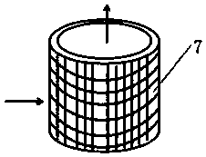
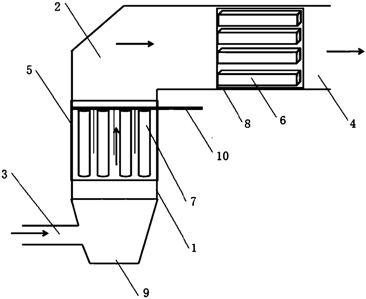
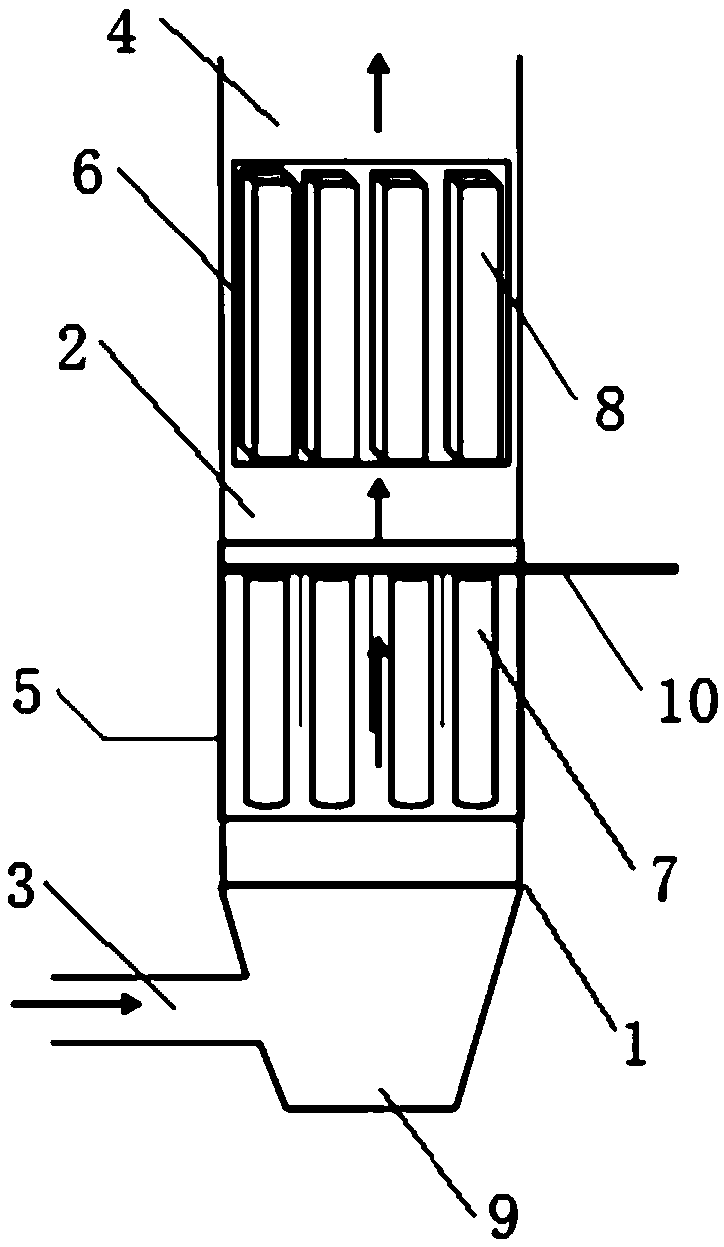
[0023] Such as Figure 1 to Figure 3 Shown: an integrated device for dust removal and denitrification of high-temperature flue gas, including a fuselage 1 that constitutes a flue gas channel 2 inside. The high-temperature dust collector 5 and the SCR denitrification reactor 6 are detachably installed in the fuselage 1 along the direction of flue gas passage. The top end of the cylinder 7 is open and the bottom end is sealed. The filter cylinder 7 includes at least one filter layer made of metal ...


PUM


Abstract

The invention discloses a high-temperature flue gas dust removal and denitration integrated device which comprises a machine body, wherein a flue gas passage is formed inside the machine body; a fluegas inlet is formed at the lower part of the machine body; a flue gas outlet is formed at the upper part of the machine body and is conducted with the flue gas passage; a high-temperature dust removerand a SCR (Selective Catalytic Reduction) denitration reactor are sequentially mounted in a detachable mode in the machine body along a direction in which flue gas passes; the high-temperature dust remover comprises a plurality of filter cartridges regularly arranged and a dust purging collection assembly; the top end of each filter cartridge is open, and the bottom end of the filter cartridge issealed; each filter cartridge comprises at least one filter layer made of a metal fiber net; a plurality of ceramic honeycomb bodies regularly arranged are arranged in the SCR denitration reactor; each ceramic honeycomb body comprises a carrier and a catalyst distributed on the carrier; each catalyst is formed by V2O5 or rare earth elements or transition elements; each carrier adopts TiO2 or a molecular sieve or cordierite. The high-temperature dust remover and the SCR denitration reactor are mounted in a detachable mode; the filter cartridges made of the metal fiber nets are adopted; for each filter cartridge, the filtering area is not limited, filter pores are regularly arranged, and a through hole rate is high; the high-temperature flue gas dust removal and denitration integrated device is long in service life and has high-temperature resistance.

Description

technical field [0001] The invention relates to a dust removal and denitrification device applied in fields such as cement plants, biomass power plants, and steel plants, and in particular to an integrated device for dust removal and denitrification of high-temperature flue gas and its technology. Background technique [0002] The denitrification and emission reduction policies for non-electricity industries are tightening day by day, and the pressure to reduce emissions in the cement, glass, biomass power plants, and steel industries has increased sharply. The flue gas of these industries often contains a large amount of pollutants such as dust and nitrogen oxides, which is the top priority of governance in recent years. Compared with boiler flue gas in thermal power plants, the flue gas in the above-mentioned fields has the characteristics of large amount of dust, high content of alkali metals in dust, and high content of nitrogen oxides. Traditional SCR technology is dire...

Claims


Application Information

Patent Timeline
Patent Type & Authority Applications(China)
IPC IPC(8): B01D53/86B01D46/24B01D53/56
CPCB01D46/2411B01D53/8631
Inventor 刘长东薛东武胡晨晖尹顺利周文
Owner ZHEJIANG ZHENENG CATALYST TECH CO LTD
Why Eureka
Try Eureka