

Process method for prolonging service life of upper electrode of etching machine table
A process method and etching machine technology, applied in metal material coating process, anodic oxidation, electrolytic coating, etc., can solve the problems that affect the production capacity of the equipment, the yield rate of the glass substrate, the particles at the pores, and the inability to meet the use requirements, etc., to achieve excellent Plasma etching gas corrosion resistance, excellent plasma etching gas corrosion resistance, and high compactness
- Summary
- Abstract
- Description
- Claims
- Application Information
AI Technical Summary
Problems solved by technology
Method used
Image


Examples
Embodiment 1
[0043] A process for improving the service life of electrodes on an etching machine, comprising the following steps
[0044] (1) The upper electrode is an aluminum component, which is degreased and polished first;
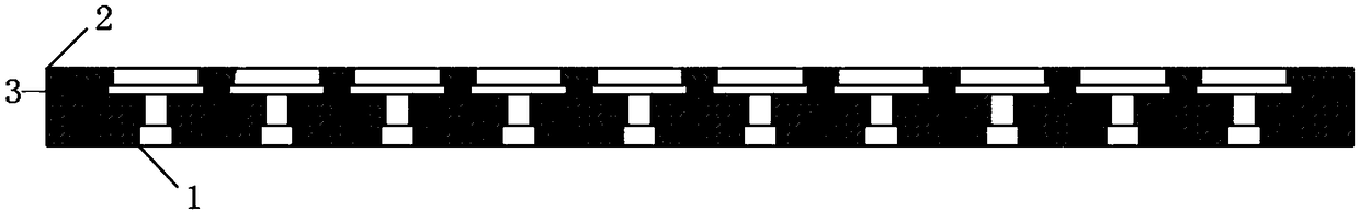
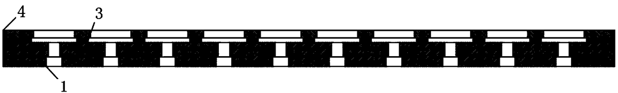
[0045] (2) Masking before sandblasting: use figure 2 The structure shown is set to be protected before sandblasting, and only 5-12mm around the air hole is roughened by sandblasting. figure 2 The thickness of the sandblasting protection fixture is 3mm, the material is Al or SUS, and the aperture of the fixture is 6mm. Use heat-resistant double-sided tape to adhere the fixture and upper electrode;
[0046] (3) Sandblasting: use white corundum sand material, mesh number 60#, sandblasting pressure 0.3Mpa, sandblasting distance 300mm, after sandblasting, the roughness around the pores reaches Ra 3.5μm;
[0047] (4) Cleaning and drying: Remove the masking on the surface of the upper electrode, first use a dust-free cloth dipped in acetone to remove the residual glu...
Embodiment 2
[0056] A process for improving the service life of electrodes on an etching machine, comprising the following steps
[0057] (1) The upper electrode is an aluminum component, which is degreased and polished first;
[0058] (2) Masking before sandblasting: use figure 2 The structure shown is set to be protected before sandblasting, and only 12mm around the air hole is roughened by sandblasting. figure 2 The thickness of the protective tool for medium sandblasting is 5mm, the material is Al or SUS, and the hole diameter of the tool is 10mm. In order to prevent the jig from sliding against the surface of the upper electrode under the action of sand or compressed air during the sandblasting process, resulting in wrong sandblasting range and scratches on the surface of the upper electrode, use figure 2 The shown double-sided tape is attached to the jig and top electrode;
[0059] (3) Sandblasting: use white corundum sand material, mesh number 100#, sandblasting pressure 0.5Mp...
PUM
| Property | Measurement | Unit |
|---|---|---|
| Roughness | aaaaa | aaaaa |
| Thickness | aaaaa | aaaaa |
| Roughness | aaaaa | aaaaa |
Abstract
Description
Claims
Application Information