A kind of wear-resistant ceramic preform casting device and casting process

A technology of wear-resistant ceramics and prefabricated parts, applied in the direction of manufacturing tools, supply devices, etc., can solve the problems of long production cycle, high production cost, complicated preparation process, etc., and achieve the goal of saving energy consumption, reducing equipment investment, and reducing production costs Effect

Active Publication Date: 2021-02-09
上海邦聚工程材料技术有限公司
View PDF2 Cites 0 Cited by
  • Summary
  • Abstract
  • Description
  • Claims
  • Application Information

AI Technical Summary

Problems solved by technology

[0006] The technical problem to be solved by the present invention is to provide a casting device for wear-resistant ceramic preforms, which can solve the problems of complex preparation process, high production cost and long production cycle of wear-resistant ceramic preforms in the prior art

Method used


Image

  • A kind of wear-resistant ceramic preform casting device and casting process
  • A kind of wear-resistant ceramic preform casting device and casting process

Examples


Embodiment 1

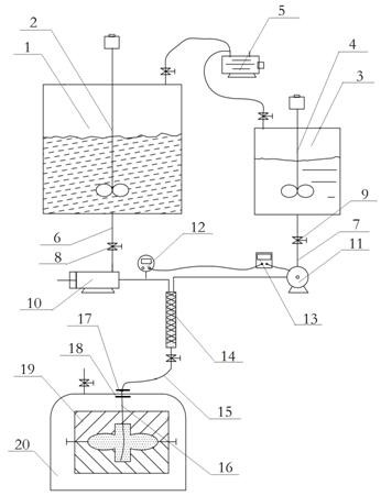
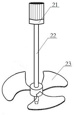
[0029] Such as figure 1 As shown, a casting device for wear-resistant ceramic preforms includes a first stirred tank 1, a second stirred tank 3, a static mixer 14, a casting mold 19 and a vacuum chamber 20, the first stirred tank 1 and the second stirred tank 3 A first stirring device 2 and a second stirring device 4 are respectively arranged inside, and the first stirring device 2 and the second stirring device 4 have the same structure. The first stirred tank 1 and the second stirred tank 3 are respectively connected with a vacuum pump 5, the first vacuum pump 5 is connected with the first stirred tank 1 and the second stirred tank 3 through an on-off valve, and the function of the vacuum pump 5 is to remove the first stirred tank 1 The air entrained in the sample injection process with the second stirred tank 3 prevents the air from being mixed into the slurry with the stirring device, entraining air bubbles inside the slurry, and the thick slurry makes the air bubbles unab...

Embodiment 2

[0037] The wear-resistant ceramic preform casting device of this embodiment is roughly the same as that of Embodiment 1, the difference is that the mold cavity of the casting mold 19 is a simple cylinder, the casting mold 19 is placed outside the vacuum chamber 20, and the static mixer 14 is passed through a hose. The cavity bottom of the casting mold 19 is connected.

[0038] A casting process for wear-resistant ceramic prefabricated parts, the prefabricated part is cylindrical in shape, comprising the following steps: (1) adding 4kg bisphenol A type epoxy resin (epoxy equivalent is 175~190), 4kg Bisphenol F type epoxy resin (epoxy equivalent is 160~175), 30kg silicon carbide powder, 5kg alumina powder; Add 8kg polyamide, 0.4kg silane coupling agent, 0.2kg DMP- 30 curing accelerator, 0.2kg fumed silica; turn on the vacuum pump 5, vacuumize the first stirred tank 1 and the second stirred tank 3 to a vacuum degree of 0.08MPa, start the first stirring device 2 and the second sti...


PUM


Abstract

The invention discloses a casting device for wear-resistant ceramic preforms, which includes a first stirred tank, a second stirred tank, a static mixer, a casting mold, a vacuum pump and a vacuum chamber, the first stirred tank and the second stirred tank are connected to the vacuum pump , the first stirred tank and the second stirred tank are respectively connected to the static mixer through the first delivery pipe and the second delivery pipe, the static mixer is connected to the casting mold, and the first delivery pipe is provided with A plunger pump and a flow meter, the second delivery pipe is provided with a diaphragm pump and a flow controller, the flow meter is connected to the flow controller, and the flow controller is connected to the diaphragm pump. The wear-resistant ceramic preform casting device and casting process of the present invention do not need to clean the first stirring tank and the second stirring tank, which improves the production efficiency, and the entire casting process can be completed at normal temperature, reducing the investment in equipment for the oven, Energy consumption is saved, and it is helpful for mass production of wear-resistant ceramic prefabricated parts.

Description

technical field [0001] The invention relates to the industrial technical field of fluid equipment such as a pump body, a valve, a pipeline, and a fan, and in particular relates to a casting device and a casting process for a wear-resistant ceramic prefabricated part. Background technique [0002] Using epoxy resin or vinyl resin as adhesive, adding wear-resistant particles such as silicon carbide and aluminum oxide as raw materials, and reacting with amine curing agent to harden, it can be cured at room temperature to form a composite ceramic wear-resistant coating, which has been proven to be Adhesive repair and protection of metal equipment. This type of material has a simple construction process, can be cured at room temperature, and has no thermal stress deformation. It has been widely used in the field of industrial equipment maintenance and protection. However, the application of large-area casting to form prefabricated parts involves many few. [0003] The invention ...

Claims


Application Information

Patent Timeline
Patent Type & Authority Patents(China)
IPC IPC(8): B28B13/02
CPCB28B13/02
Inventor 邬苏焕丁芳
Owner 上海邦聚工程材料技术有限公司
Why Eureka
Try Eureka