Solenoid valve drive device and drive method

A solenoid valve drive, solenoid valve technology, applied in the direction of the valve device, valve operation/release device, valve details, etc., can solve the problems of slow response time of relays, increase product energy consumption, unfavorable equipment protection, etc., to achieve stable protection and operation Performance and operational safety, low manufacturing cost and maintenance cost, high practical value and promotional value

Active Publication Date: 2018-12-18
河南华索科技有限公司
View PDF8 Cites 5 Cited by
  • Summary
  • Abstract
  • Description
  • Claims
  • Application Information

AI Technical Summary

Problems solved by technology

[0003] The main feature of this control method is that the solenoid valve needs to work at full power all the time, which greatly increases the energy consumption of the product, leads to an increase in the heat generation of the equipment, and thus greatly increases the failure rate of the equipment. Maintain and repair the equipment, which greatly improves the cost of using the product
In addition, the response time of the relay is slow, which has a certain impact on the normal production process of the equipment; when the contacts of the relay are closed or disconnected, an arc will be generated, which will cause electromagnetic interference to the digital signal system and affect the normal use of the digital signal system; At the same time, the entire device lacks overload and short-circuit protection, and there is no fault indication structure, which is not conducive to the protection of the use of the device, and it is difficult to repair the device in time when it fails
[0004] To sum up, the research and development of the driving method and device of the solenoid valve of the terminal control equipment is to overcome the problem of high energy consumption and high heat generation caused by the high power consumption of the solenoid valve when it is always working at full power. very necessary

Method used


Image

  • Solenoid valve drive device and drive method
  • Solenoid valve drive device and drive method
  • Solenoid valve drive device and drive method

Examples


Embodiment 1

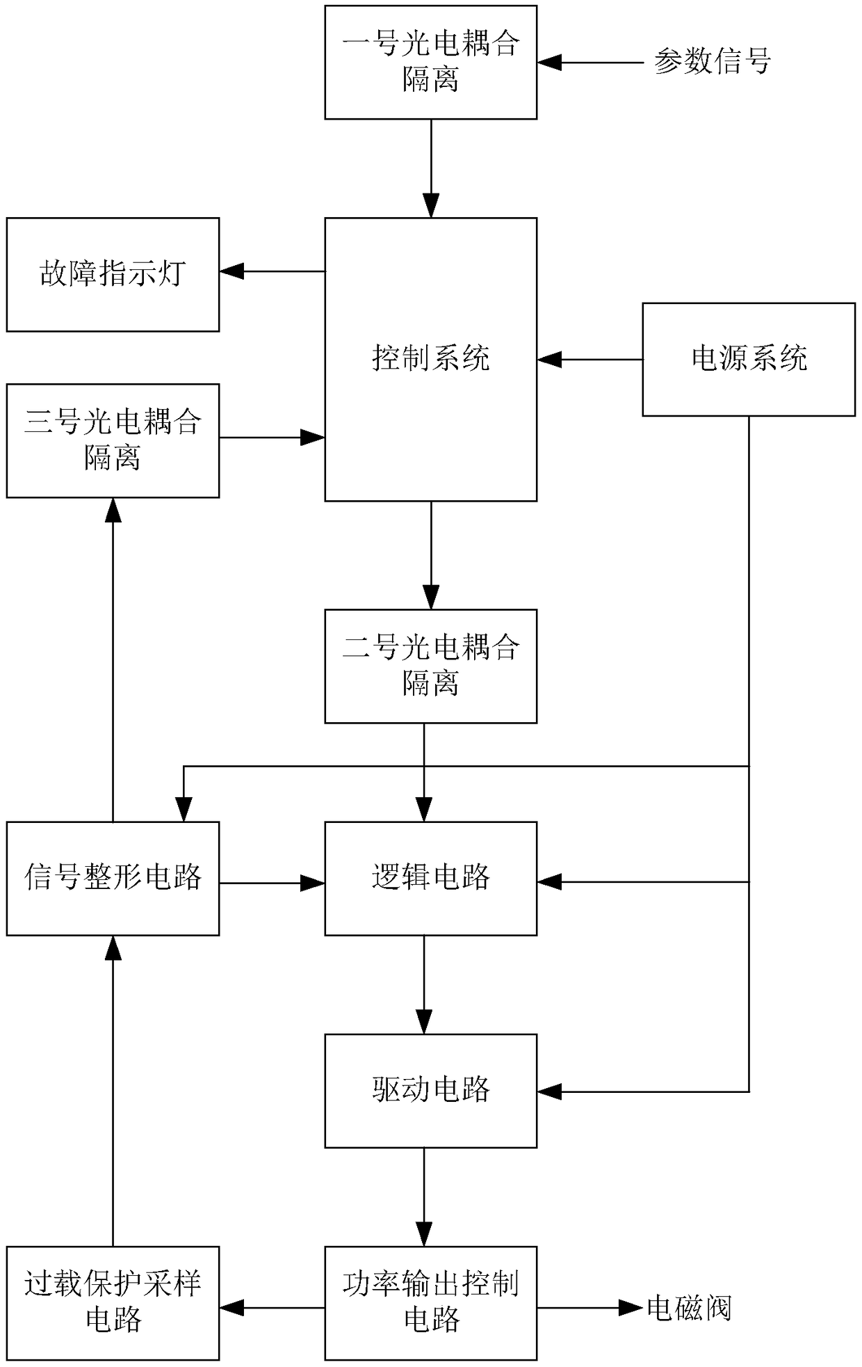
[0043] Such as figure 1 As shown, a solenoid valve drive device includes a control system, a power supply system, a logic circuit, a drive circuit, a power output control circuit, an overload protection sampling circuit and a signal shaping circuit.

[0044] The control system can accept parameter signals, the logic circuit is connected to the control system, the drive circuit is connected to the logic circuit, the power output control circuit is connected to the drive circuit and used to control the solenoid valve, and the overload protection sampling circuit is connected to the power output control circuit. Connection, the signal shaping circuit is connected with the overload protection sampling circuit, and the power supply system provides full power supply to each circuit in the whole device, and the power supply voltage is DC+5V or DC+8V or AC220V.

[0045] The specific circuit for the power system to convert 220V AC power into +5V or +8V DC power is a conventional techni...

Embodiment 2

[0088] This embodiment discloses a method for driving a solenoid valve, which includes the following operating steps:

[0089] (1) Connect the solenoid valve driving device to the solenoid valve through the power output control circuit;

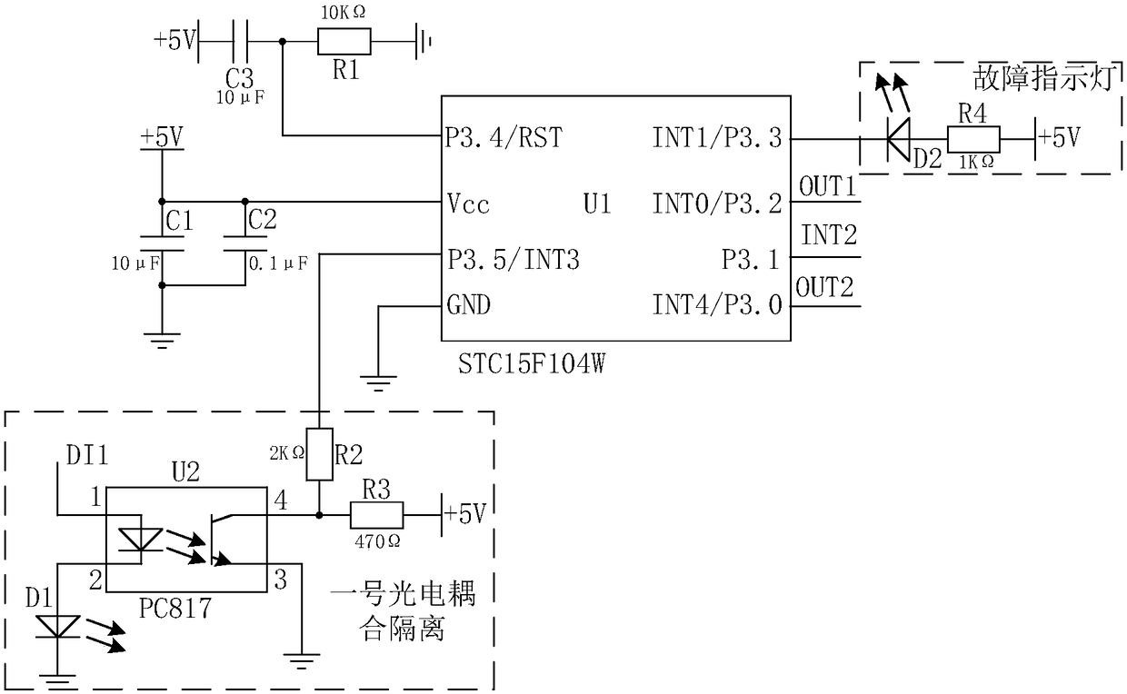
[0090] (2) Through the computer, the parameter signal is imported into the single-chip microcomputer chip of the control system in real time through No. 1 photoelectric coupling isolation;

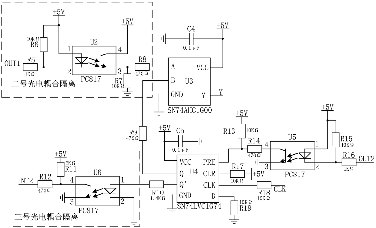
[0091] (3) The control system generates a PWM drive control signal according to the imported parameter signal, and outputs it through the No. 2 photoelectric coupling isolation;

[0092] The initial pulse width of the generated PWM drive control signal is relatively wide, so that the solenoid valve can have enough driving force to pull in. After the solenoid valve pulls in, the PWM drive control signal with a low pulse width is periodically output to So that the solenoid valve can maintain the pull-in state;

[0093] Such as Figure 8 shown, t 1 is th...


PUM


Abstract

The invention discloses a solenoid valve drive device. The solenoid valve drive device comprises a control system capable of receiving parameter signals, a power system supplying power to the controlsystem, a logic circuit connected with the control system, a drive circuit connected with the logic circuit, a power output control circuit connected with the drive circuit and used for controlling asolenoid valve, an overload protection sampling circuit connected with the power output control circuit and a signal shaping circuit connected with the overload protection sampling circuit. Accordingto the solenoid valve drive device, energy consumption and the heating value of products can be effectively reduced, then the service life of the products is prolonged, the failure rate of the products is reduced, the maintenance frequency of the products is further reduced, and therefore consumption of enterprise production funds is reduced.

Description

technical field [0001] The invention belongs to the field of solenoid valve driving, and specifically refers to a solenoid valve driving device and a driving method thereof. Background technique [0002] During the production and roasting of anode carbon blocks, the gas supply needs to be precisely controlled. During the gas supply process, the gas supply needs to be adjusted in real time according to the actual production situation and demand. In the current industrial production process control system, The adjustment process is generally done through a solenoid valve. In today's production equipment, the solenoid valve of the terminal control equipment is generally driven and controlled by a relay, and the relay is generally controlled by the control system according to the production process parameters, thereby achieving the effect of controlling the on-off of the solenoid valve. [0003] The main feature of this control method is that the solenoid valve needs to work at...

Claims


Application Information

Patent Timeline
Patent Type & Authority Applications(China)
IPC IPC(8): F16K31/06F16K37/00
CPCF16K31/0675F16K37/0058Y02P90/02
Inventor 郭力李霖顾一鸣冯聪聪陈建红
Owner 河南华索科技有限公司
Why Eureka
Try Eureka