A decoupling control method for a suspension system of a four-degree-of-freedom magnetic levitation motor

A decoupling control and decoupling controller technology, applied in the direction of motor generator control, electronic commutation motor control, control system, etc., can solve the problems of slow convergence speed, good generalization performance, difficult to determine the accuracy of the magnetic levitation control system model, etc. problem, to achieve the effect of improving dynamic performance, simplifying control steps, and getting rid of dependence

Active Publication Date: 2018-12-18
JIANGSU UNIV
View PDF6 Cites 8 Cited by
  • Summary
  • Abstract
  • Description
  • Claims
  • Application Information

AI Technical Summary

Problems solved by technology

The decoupling of BP neural network and RBF neural network solves the problem that it is difficult to establish an accurate mathematical model, but its learning has a slow convergence speed and is easy to fall into a local minimum point; and in the case of optimizing the parameters of the support vector machine without an intelligent algorithm Under these conditions, the accuracy of the maglev control system model learned by the support vector machine is difficult to determine; the extreme learning machine is a single hidden layer feed-forward neural network, which does not require a large amount of data in the process of realizing the maglev control system modeling process, only needs to set the network hidden layer structure In the process of simulating the algorithm, there is no need to adjust the network input weights and the bias of hidden elements, and a unique optimal solution is generated, so the algorithm is fast and has good generalization performance

Method used


Image

  • A decoupling control method for a suspension system of a four-degree-of-freedom magnetic levitation motor
  • A decoupling control method for a suspension system of a four-degree-of-freedom magnetic levitation motor
  • A decoupling control method for a suspension system of a four-degree-of-freedom magnetic levitation motor

Examples


Embodiment Construction

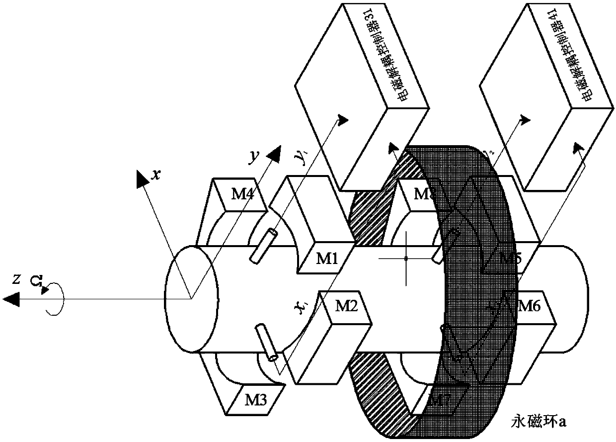
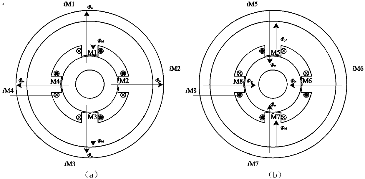
[0025] Such as figure 1 and 2 As shown, the levitation system of the four-degree-of-freedom magnetic levitation motor consists of a permanent magnet ring a, a rotor, and 8 magnetic poles M1-M8 on the stator, and 8 control coils iM are wound on the magnetic poles respectively. 1 ~iM 8 To form, the magnetic pole coils on the same degree of freedom are connected in series, controlled by the same direct current, that is, iM 1 , iM 3 in series, iM 2, iM 4 in series, iM 5 , iM 7 Tandem and iM 6 , iM 8 connected in series, direct current is passed through the coil respectively to excite i y1 i x1 i y2 i x2 , the center of the rotor is balanced at the geometric center of the stator.

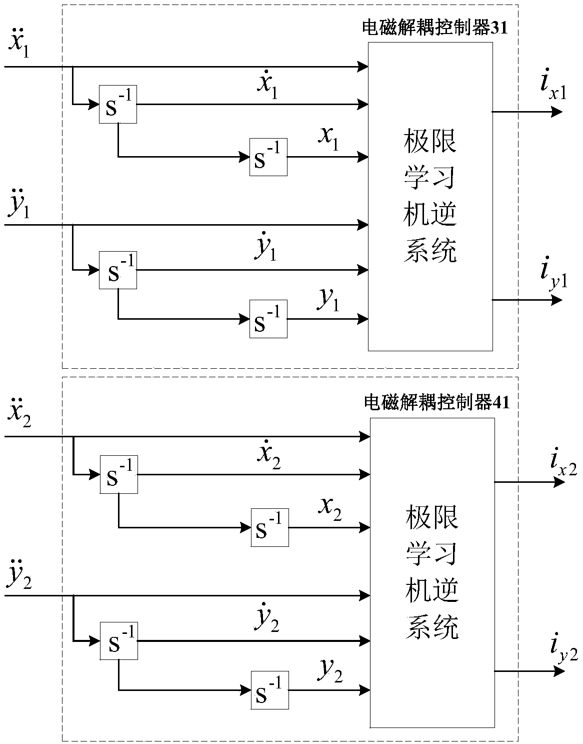
[0026] Such as image 3 As shown, the electromagnetic decoupling controllers 31, 41 respectively use the second derivative of the displacement deviation and Is the input, the output controls the DC excitation current i of the bearing movement x1 i y1 with i x2 i y2 , the rotor of th...


PUM


Abstract

The invention discloses a decoupling control method for a suspension system of a four-degree-of-freedom magnetic levitation motor, which is divided into a suspension system and a torque system. In thesuspension system, there is electromagnetic coupling between the front displacement x1, y1 and the rear displacement x2, y2 in the radial direction, and the coaxial displacement between x1 and x2, y1and y2 will influence each other, so there is mechanical coupling. In order to solve these two kinds of coupling, the input of the controlled object is the current in the suspension winding, and theoutput is the front and rear displacement of the suspension rotor. Two closed-loop controllers are designed to control the front and rear displacement respectively. The displacement sensor is used todetect the radial displacement of the rotor and the displacement signal is fed back to the closed-loop controller. Electromagnetic decoupling controller is constructed to solve the electromagnetic coupling between the front and rear sides of the rotor, and mechanical decoupling controller is constructed to output compensation current to the suspension winding to solve the mechanical coupling.

Description

technical field [0001] The present invention generally relates to a levitation system of a magnetic levitation motor, and specifically relates to a construction method of a rotor electromagnetic decoupling and mechanical decoupling controller of a levitation system, which is suitable for the balance control of a high-speed rotor of a magnetic levitation system, provides conditions for its support, and belongs to high-speed and ultra-high-speed field of electrical transmission. Background technique [0002] Most ordinary motors use mechanical bearings. Due to the existence of mechanical wear, the frictional resistance of the rotor is increased, the moving parts are damaged, and mechanical vibration and noise are generated. Seriously, it will cause uneven breath, winding heating, increased temperature rise, and decreased temperature. The efficiency of the motor shortens the life of the motor. [0003] The magnetic levitation motor suspension system uses electromagnetic force ...

Claims


Application Information

Patent Timeline
Patent Type & Authority Applications(China)
IPC IPC(8): H02P21/00
CPCH02P21/0003
Inventor 孙玉坤崔强袁野杨帆朱志莹黄永红
Owner JIANGSU UNIV
Why Eureka
Try Eureka