Soot blowing system and method for SCR (Selective Catalytic Reduction) reactor

A technology of SCR reactor and soot blowing system, which is applied in the field of soot blowing and SCR reactor soot blowing system, which can solve the problems of increasing the difficulty of operation and maintenance of SCR reactor, reducing the reliability of SCR reactor, and complicated purge pipeline , to achieve the effect of not easy to cause failure, simple structure and good purging effect

Active Publication Date: 2018-12-21
HARBIN ENG UNIV
View PDF9 Cites 5 Cited by
  • Summary
  • Abstract
  • Description
  • Claims
  • Application Information

AI Technical Summary

Problems solved by technology

In addition, the system involves many electromagnetic valves, which greatly reduces the reliability of the SCR reactor and increases the difficulty of operation and maintenance of the SCR reactor.
[0005] In summary, the existing SCR reactors have problems such as large gas consumption, low purge efficiency, complex purge pipelines, and easy formation of new ash accumulation areas. Develop and design a set of SCR reactors that are economical, efficient, and easy to operate and maintain. The soot blowing system of the SCR reactor is necessary, and the present invention proposes a soot blowing system of the SCR reactor and a soot blowing method realized by this system in view of the deficiencies of the prior art

Method used


Image

  • Soot blowing system and method for SCR (Selective Catalytic Reduction) reactor
  • Soot blowing system and method for SCR (Selective Catalytic Reduction) reactor
  • Soot blowing system and method for SCR (Selective Catalytic Reduction) reactor

Examples


Embodiment Construction

[0031] The present invention will be further described below in conjunction with the accompanying drawings.

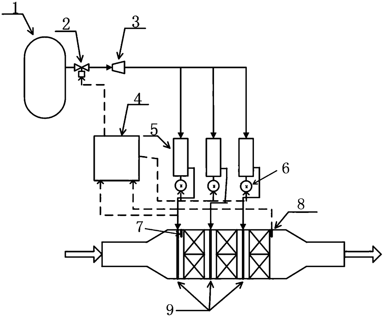
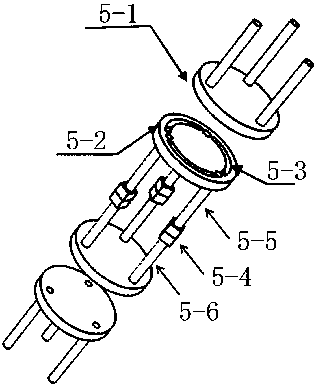
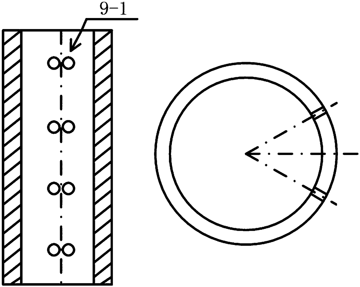
[0032] combine Figure 1 to Figure 3 , the present invention proposes a SCR reactor soot blowing system, which is mainly composed of an air bottle, a decompression system, a control system, a rotary pressure pulse converter, and a power unit. The soot blowing pipeline of the SCR reactor soot blowing system proposed by the present invention is a stainless steel pipeline with regularly arranged soot blowing holes, and the variable pressure compressed air generated by the rotary pressure pulse converter is used to control the SCR reactor. The dust accumulated on the surface of the catalyst is purged.

[0033] When the pressure difference between the inlet and outlet of the SCR reactor is large, the control system 4 of the soot blowing system will automatically turn on the dust purge mode. The compressed air solenoid valve 2 is opened, and the compressed air in the air b...


PUM


Abstract

The invention provides a soot blowing system for an SCR (Selective Catalytic Reduction) reactor and a soot blowing method implemented by the system, and belongs to the technical field of marine dieselengine tail gas posttreatment. The soot blowing system in the invention takes compressed air as purging gas, and comprises an air bottle, a decompression module, a control module, a rotary pressure pulse converter, a rotary power device and a soot blowing pipeline. When the flue gas pressure at the inlet / outlet of the SCR reactor exceeds a set value, a controller of the soot blowing system automatically starts deposited soot blowing, the compressed air in the air bottle is conveyed to the top of the rotary pressure pulse converter through a pressure reducer, and the rotary pressure pulse converter can rotate to drive the soot blowing pipeline to produce purging gas of different pressures over time in order to form strong turbulent disturbance on the surface of a catalyst, thereby improving the purging effect. The soot blowing pipeline is reasonably arranged, and can effectively avoid secondary soot accumulation. At the same time, a soot blowing hole is located in the soot blowing pipeline, and has a simple structure, thereby facilitating later maintenance.

Description

technical field [0001] The invention belongs to the technical field of marine diesel engine tail gas post-treatment, and in particular relates to a soot blowing system for an SCR reactor and a soot blowing method realized by the system. Background technique [0002] SCR technology is currently the most widely used denitrification technology for ships. Marine diesel engines burn low-quality fuel, and there is a lot of dust in the exhaust gas of diesel engines. In addition, the flue gas entering the SCR reactor contains a small amount of urea crystals and sulfate and other components, and the ash deposited on the surface of the SCR reactor catalyst will reduce the effective catalytic area of ​​the catalyst and greatly affect the denitrification performance of the SCR system. Many researchers at home and abroad have studied the soot blowing device of the SCR system, but there are still problems in the soot blowing system of the SCR reactor, which leads to the decline in the pe...

Claims


Application Information

Patent Timeline
Patent Type & Authority Applications(China)
IPC IPC(8): B01D53/94B01D53/56
CPCB01D53/9418
Inventor 周松张钊朱元清冯永明
Owner HARBIN ENG UNIV
Why Eureka
Try Eureka