

3D printing device using block unit
A 3D printing and block unit technology, applied in the field of 3D molding, can solve the problems of unfavorable fiber mechanical properties, long printing time, improving equipment utilization time and manufacturing cost, etc.
- Summary
- Abstract
- Description
- Claims
- Application Information
AI Technical Summary
Problems solved by technology
Method used
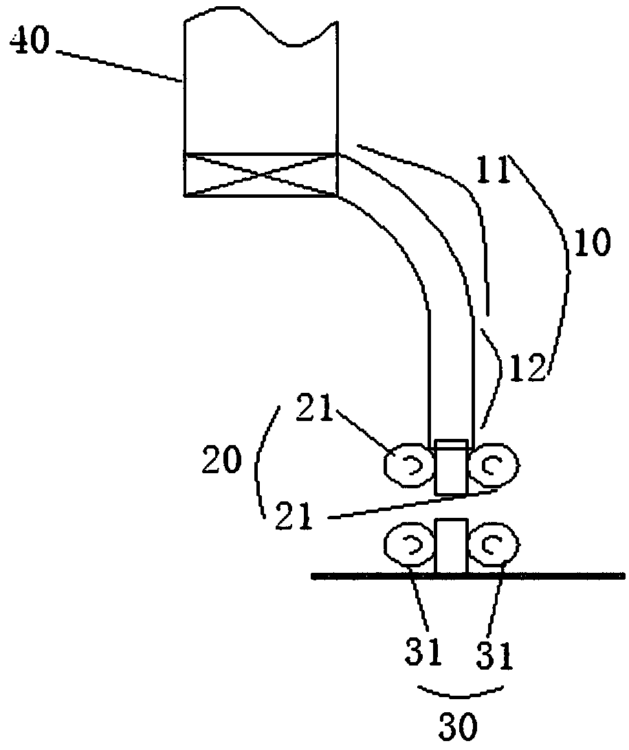
Image

Examples
Embodiment 1
[0081] The printed structure obtained by printing with the device bonding block unit
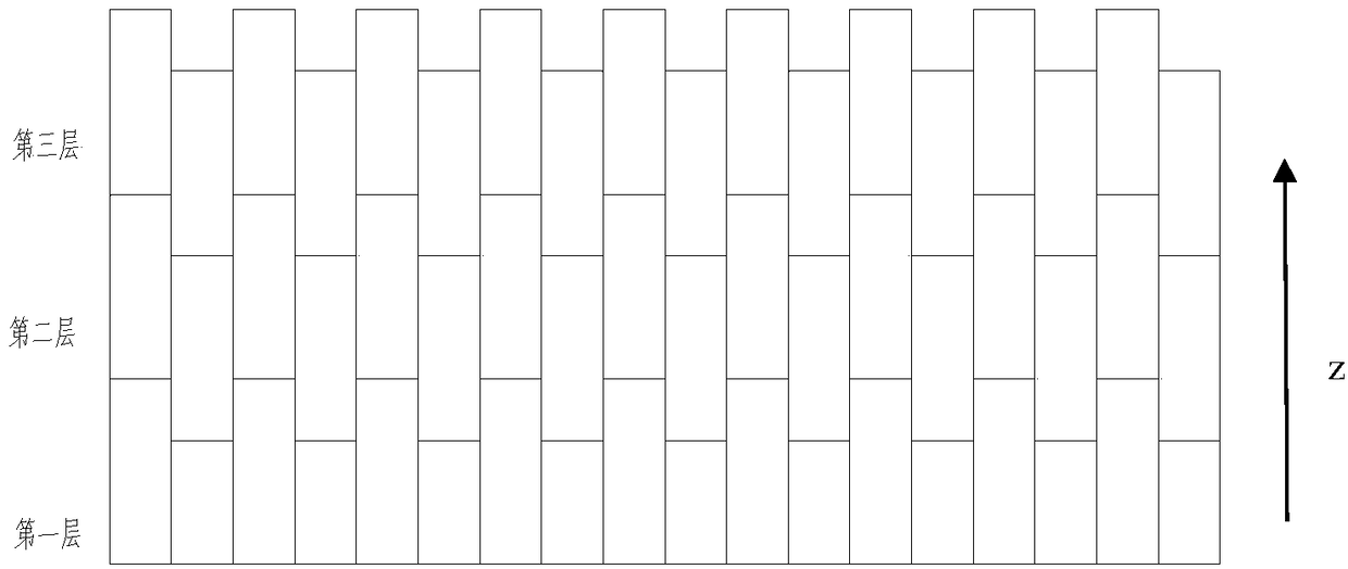
[0082] figure 1 It shows a three-layer printing structure formed by printing with bonded block units. The block unit has a fiber content of 65%v, a size of 5mm×5mm×10mm, and a fiber content of 65%v, and a size of 5mm×5mm×15mm. The materials are carbon fiber reinforced PA6 with smooth surface and coated with epoxy quick-drying adhesive. Printing form: two kinds of blocks are arranged alternately in the first layer, and one kind of block of 5mm×5mm×15mm is used in the next two layers.
[0083] Effect: After using this printing form, on the material, the unit with high fiber content is used to increase the overall fiber content of the block unit; in the printing form, the gaps between the printing layers are alternately staggered, which improves the crack resistance between layers and ensures the Z direction Excellent mechanical properties; in terms of printing speed, the printing speed of th...
Embodiment 2
[0085] The printed structure obtained by printing with the solder block unit of the device
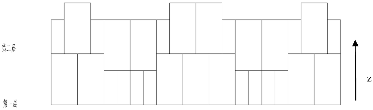
[0086] figure 2 It shows a two-layer printing structure formed by printing with soldered block units. The block unit has a fiber content of 60%v and a size of 10mm×10mm×15mm and a fiber content of 60%v and a size of 5mm×10mm×10mm. The material Both are carbon fiber reinforced PP, and there are multiple welding lines with a height of 0.5mm (adjacent distance: 2mm) on the surface. Printing form: two layers use block units of two sizes and are arranged according to a certain rule.
[0087] Effect: After using this printing form, the fiber content of the printed part is increased to 60% v; the mechanics of the printed part in all directions is improved, and the crack resistance of the part is improved; in terms of printing speed, the printing speed of the whole body is increased to the original 8 times.
PUM
| Property | Measurement | Unit |
|---|---|---|
| tensile strength | aaaaa | aaaaa |
| height | aaaaa | aaaaa |
Abstract
Description
Claims
Application Information