Vertical PECVD compound PVD vacuum coating system

A vacuum coating, vertical technology, applied in the direction of vacuum evaporation coating, overlay coating, sputter coating, etc., can solve the problems of poor film uniformity and low ionization rate, and achieve low production cost and prevent ionization Pollution, the effect of ensuring film quality

Pending Publication Date: 2018-12-21
苏州善柔真空科技有限公司
View PDF1 Cites 4 Cited by
  • Summary
  • Abstract
  • Description
  • Claims
  • Application Information

AI Technical Summary

Problems solved by technology

[0003] The purpose of the present invention is to provide a vertical PECVD composite PVD vacuum coating system, which s

Method used


Image

  • Vertical PECVD compound PVD vacuum coating system
  • Vertical PECVD compound PVD vacuum coating system
  • Vertical PECVD compound PVD vacuum coating system

Examples


Example Embodiment

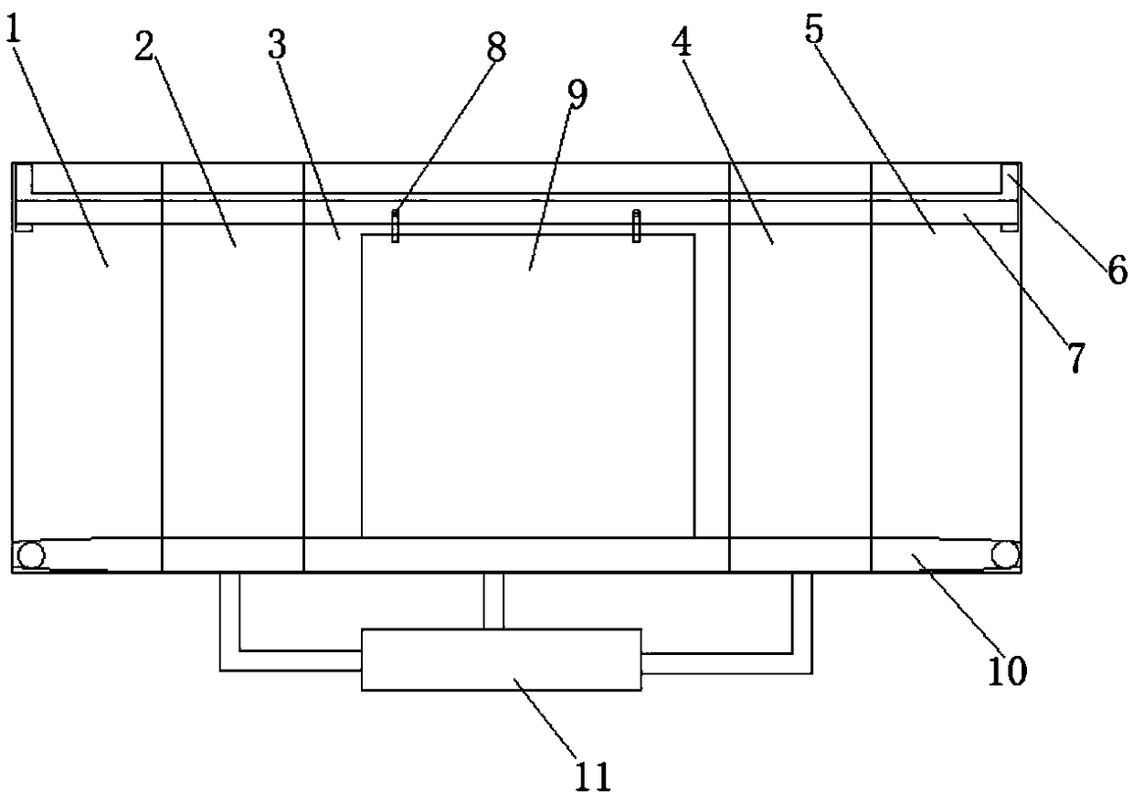
[0022] The present invention is a vertical PECVD composite PVD vacuum coating system, the structure is as follows Figure 1~Figure 3 As shown, it includes a feeding cavity 1, a preheating cavity 2, a coating cavity 3, a buffer cavity 4, and a discharging cavity 5 which are closely connected in sequence. The feeding cavity 1 and the discharging cavity 5 are in an atmospheric environment, and the preheating cavity 2, Both the coating chamber 3 and the buffer chamber 4 are connected with a vacuum pumping system 11. The top of the coating chamber 3 is welded with a rail 6, a substrate frame 7 is sleeved in the rail 6, and a substrate 9 is hung on the substrate frame 7 through a hook 8. The bottom of the substrate 9 is located on the conveyor belt 10, and the conveyor belt 10 is connected to the bottom of the coating chamber 3 through a transmission roller.

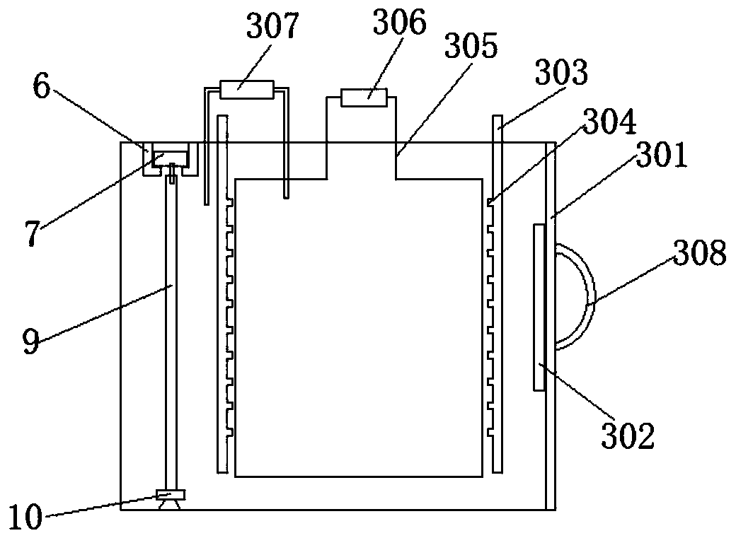
[0023] The coating chamber 3 is provided with a PVD magnetron sputtering device, a gas release device and a PECVD device. The P...


PUM


Abstract

The invention discloses a vertical PECVD compound PVD vacuum coating system. The vertical PECVD compound PVD vacuum coating system comprises a feeding cavity, a preheating cavity, a coating cavity, abuffer cavity and a discharge cavity, wherein the feeding cavity, the preheating cavity, the coating cavity, the buffer cavity and the discharge cavity are tightly connected with one another in sequence, the feeding cavity and the discharge cavity are in atmospheric environment. The preheating cavity, the coating cavity and the buffer cavity are connected with a vacuum pumping system. A rail is welded to the top of the coating cavity, and a base material frame is connected in the rail in a sleeving mode. A base plat is hung on the base material frame through hooks, the bottom of the base plateis located on a conveying belt, and the conveying belt is connected to the bottom of the coating cavity through drive rollers. The existing problem that poor uniformity and low ionization rate of thin film coated by a coating device in the prior art is solved.

Description

technical field [0001] The invention belongs to the technical field of coating devices, and relates to a vertical PECVD composite PVD vacuum coating system. Background technique [0002] The patent document whose application number is CN107541713A discloses a "diamond-like thin film continuous coating device", which includes a shelf chamber, a first vacuum transition chamber, a magnetron sputtering process chamber, an atmosphere isolation chamber, a DLC coating chamber, The second vacuum transition chamber and the shelf chamber. When the device prepares a thin film, a transition layer is firstly coated in the process chamber, and then transferred to the coating chamber to continue coating. The coating method in the coating chamber is reactive magnetron sputtering. However, there are some problems in the design of the coating chamber of this device. For example, the working gas is introduced from the bottom side of the chamber, which will cause poor uniformity of gas distri...

Claims


Application Information

Patent Timeline
IPC IPC(8): C23C14/35C23C14/56C23C16/54C23C16/513C23C28/00
CPCC23C14/35C23C14/568C23C16/513C23C16/54C23C28/00
Inventor 李宏霞张克伟林朝宗谢倩
Owner 苏州善柔真空科技有限公司
Why Eureka
Try Eureka