Secondary stress isolation structure applied to MEMS force sensitive device

A stress isolation and sensitive structure technology, applied in the direction of microstructure devices composed of deformable components, microstructure technology, microstructure devices, etc., can solve the problems of stress insensitivity, non-negligible, thermal characteristics mismatch, etc., to achieve The structure and process are simple, the stress isolation is comprehensive, and the effect of reducing stress sources

Pending Publication Date: 2019-01-01
NANJING UNIV OF SCI & TECH
View PDF4 Cites 3 Cited by
  • Summary
  • Abstract
  • Description
  • Claims
  • Application Information

AI Technical Summary

Problems solved by technology

The stress isolation of such a scheme will inevitably fail to isolate the stress generated by the sensor chip during the MEMS process (such as the deposition of different materials, bonding and other process steps), such stress is usually caused by the temperature change of different materials before and after the completion of the process steps. The mismatch of thermal characteristics and the subsequent thermal stress cannot be ignored.
[0005] At present, relevant research has been done on the stress isolation of sensitive structural layers before. In 2016, Zhang Jing et al. proposed a self-calibrating silicon microresonant accelerometer structure (201610955241.0) that is not sensitive to stress, aiming at the problem of thermal stress generated by MEMS process steps The design scheme of the sensitive structural layer of the accelerometer is given. The fixed anchor point and the structural frame are connected by flexible beams, which improves the stress isolation effect of the MEMS process to a certain extent, but there are still some residual stress affecting signals in the sensitive structural layer. detection

Method used


Image

  • Secondary stress isolation structure applied to MEMS force sensitive device
  • Secondary stress isolation structure applied to MEMS force sensitive device
  • Secondary stress isolation structure applied to MEMS force sensitive device

Examples


Embodiment Construction

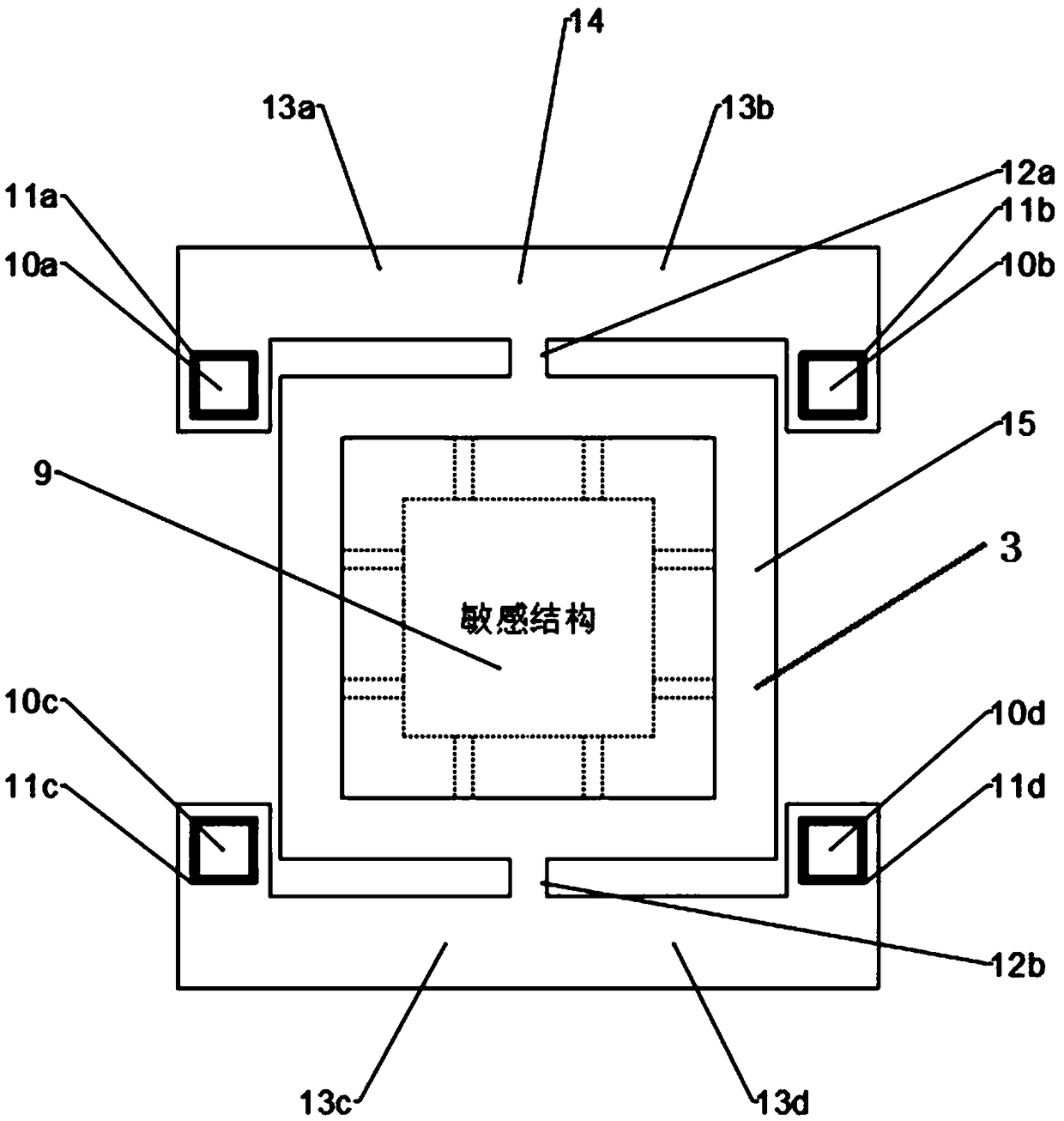
[0018] Such as figure 1 As shown, a secondary stress isolation structure 3 applied to MEMS force-sensitive devices includes an external frame structure 14 and a force-sensitive structure 9 arranged in the external frame structure 14, and the external frame structure 14 includes an internal frame 15, so The upper and lower ends of the inner frame 15 are respectively connected to the corresponding stress attenuation beam 13 through at least one stress concentration beam 12 , and the stress attenuation beam 13 is connected to the fixed anchor point 10 inside the flexible connection 11 through a plurality of flexible connections 11 .

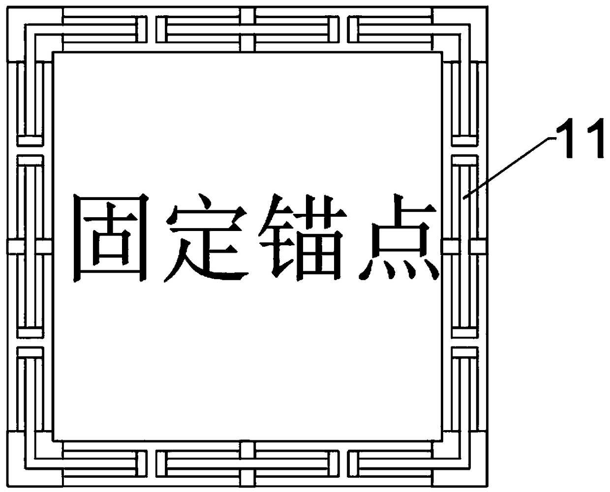
[0019] Further, the flexible connection 11 is composed of a U-shaped beam or an arched beam, such as figure 2 The flexible link 11 shown is formed by a U-shaped beam.

[0020] Further, the upper end of the inner frame 15 is connected with the upper left stress attenuation beam 13a and the upper right stress attenuation beam 13b through the upper s...


PUM


Abstract

The invention discloses a secondary stress isolation structure (3) applied to a MEMS force sensitive device. The structure comprises an external framework structure (14) and a force sensitive structure (9) arranged in the external framework structure (14). The external framework structure (14) comprises an internal framework (15). The upper and lower ends of the internal framework (15) are connected to corresponding stress attenuation beams (13) through at least one stress concentration beam (12). The stress attenuation beams (13) are connected to fixed anchor points (10) located in flexible connections (11) through the plurality of flexible connections (11). In the invention, secondary stress release can be realized; the flexible connections (11) are first order stress isolation; the stress attenuation beams (13) and the stress concentration beam (12) are stubby stiffening bars, form a transition framework and are taken as secondary stress isolation; and stresses generated during a sensitive structural technology and a packaging process can be isolated on a sensitive structural layer.

Description

technical field [0001] The invention relates to the technical field of force sensitive devices, in particular to a secondary stress isolation structure applied to MEMS force sensitive devices. Background technique [0002] MEMS sensors, or Microelectro Mechanical Systems, is a multidisciplinary cutting-edge research field developed on the basis of microelectronics technology. After more than 40 years of development, it has become one of the major scientific and technological fields attracting worldwide attention. It involves various disciplines and technologies such as electronics, machinery, materials, physics, chemistry, biology, and medicine, and has broad application prospects. Among them, MEMS pressure sensors, accelerometers, gyroscopes, etc. are typical force-sensitive devices. They are mostly used for high-precision measurement of pressure, displacement (acceleration) and attitude (angular velocity), with small size, low power consumption, and integrated circuits. ...

Claims


Application Information

Patent Timeline
Patent Type & Authority Applications(China)
IPC IPC(8): B81B3/00B81B7/02
CPCB81B3/0072B81B7/02B81B2201/0228B81B2201/0264
Inventor 张晶苏岩刘雨东
Owner NANJING UNIV OF SCI & TECH
Why Eureka
Try Eureka