
Low jitter frequency dividing clock circuit

A frequency-division clock and low-jitter technology, applied in the electronic field, can solve problems such as limited trigger output drive, sensitivity to power supply noise, and large clock jitter, and achieve reduced rising and falling edge times, strong drive capability, and low jitter characteristics Effect

Active Publication Date: 2019-01-01
CHONGQING GIGACHIP TECH CO LTD
View PDF10 Cites 8 Cited by
  • Summary
  • Abstract
  • Description
  • Claims
  • Application Information

AI Technical Summary

Problems solved by technology

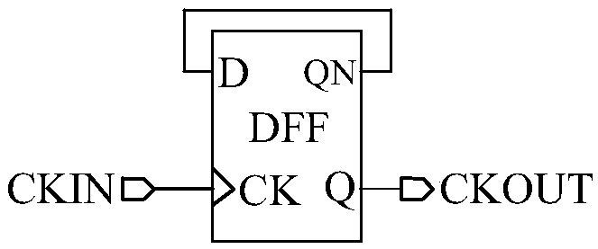
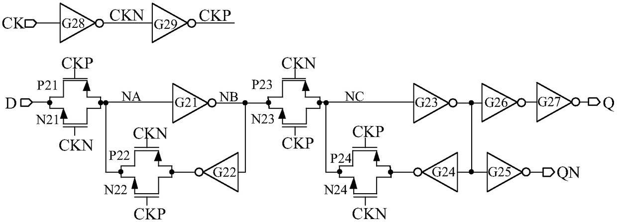
The ÷2 frequency division clock circuit often used in digital integrated circuit design is as attached figure 1 as shown, figure 1 In triggers such as figure 2 As shown, the advantage of this kind of flip-flop is that it is simple in structure and easy to implement, but its disadvantages are also obvious. The disadvantages are: first, the main clock fs to ÷2 frequency division output must pass through at least 6 or more logic gates, and the transmission path The noise of each logic gate above contributes to the noise of the output ÷ 2 frequency division clock, and the jitter is relatively large; secondly, the output of each logic gate on the transmission path is easily affected by the power supply noise, which affects the output ÷ 2 frequency division clock Noise contributes, which leads to increased jitter. The output clock of this frequency division circuit is more sensitive to power supply noise. Third, the output drive of this flip-flop is very limited. As the load increases, it must be inserted between the flip-flop output CKOUT and the load. More buffers, further leading to greater jitter on the clock signal at the load
Since the output signal-to-noise ratio of the A / D converter increases with the increase of the analog input frequency and the resolution, the A / D converter has higher and higher requirements on the clock jitter, while the clock generated by the traditional D flip-flop frequency division clock circuit The jitter is large, which can no longer meet the design requirements of high-speed and high-precision A / D converters

Method used


Image

  • Low jitter frequency dividing clock circuit
  • Low jitter frequency dividing clock circuit
  • Low jitter frequency dividing clock circuit

Examples


Embodiment Construction

[0034] Embodiments of the present invention are described below through specific examples, and those skilled in the art can easily understand other advantages and effects of the present invention from the content disclosed in this specification. The present invention can also be implemented or applied through other different specific implementation modes, and various modifications or changes can be made to the details in this specification based on different viewpoints and applications without departing from the spirit of the present invention. It should be noted that, in the case of no conflict, the following embodiments and features in the embodiments can be combined with each other.

[0035] It should be noted that the diagrams provided in the following embodiments are only schematically illustrating the basic ideas of the present invention, and only the components related to the present invention are shown in the diagrams rather than the number, shape and shape of the compo...


PUM


Abstract

The invention provides a low jitter frequency dividing clock circuit. The low jitter frequency dividing clock circuit includes a clock control signal generating circuit for generating clock signals with different phases, a low-level narrow pulse width clock control signal generating circuit for generating low-level narrow pulse width clock control signals, a high-level narrow pulse width clock control signal generating circuit for generating high-level narrow pulse width clock control signals, and a frequency division clock synthesis circuit for generating frequency division clock signals according to the low level narrow pulse width clock control signals and the high level narrow pulse width clock control signals. In the low jitter frequency dividing clock circuit, a delay of at most three logic gates is passed from a clock input terminal to a clock output terminal, so that the low jitter frequency dividing clock circuit has the advantages of less passed logic gates, smaller delay, and lower jitter, compared with a traditional D-trigger-based divide-by-2 frequency dividing clock circuit which passes delay of 6 or more logic gates. Beside, the low jitter frequency dividing clock circuit has the characteristics of stable cycle and low jitter, and can reduce rising edge time and falling edge time, thus being conductive to the low jitter characteristic, guaranteeing that the output phase difference of a trigger is fixed, and having a stronger driving capability.

Description

technical field [0001] The invention relates to the field of electronics, in particular to a low-jitter frequency division clock circuit. Background technique [0002] With the development of 5G communication, Internet of Things and big data technology, the system processing signal bandwidth is getting wider and wider, and the bandwidth of wireless signal reception is also getting wider and wider, which requires the continuous increase of the instantaneous bandwidth of the A / D converter, which in turn requires the A / D Converter sampling rates are getting higher and higher. The sampling rate of a single-channel A / D converter is always limited by factors such as the device's characteristic speed, parasitic effects, and limited rise and fall times of the clock. [0003] At present, in order to further increase the sampling rate of the A / D converter, one of the mainstream technologies is to use time interleaving technology, using multiple channels to sample, quantize and encode...

Claims


Application Information

Patent Timeline
Patent Type & Authority Applications(China)
IPC IPC(8): H03K23/44
CPCH03K23/44H03K5/15026H03K23/425H03K23/42H03K23/662H03K23/52H03K23/50H03K3/356017
Inventor 刘涛王健安王育新陈光炳付东兵李儒章胡盛东张正平罗俊徐代果邓民明王妍
Owner CHONGQING GIGACHIP TECH CO LTD
Learn More