Multi-channel digital signal optical fiber transmission test device

A test equipment, optical fiber transmission technology, applied in transmission systems, electromagnetic wave transmission systems, electrical components, etc., can solve the problems of network system paralysis, error code, response, etc. Effect

Active Publication Date: 2019-01-04
10TH RES INST OF CETC
View PDF8 Cites 4 Cited by
  • Summary
  • Abstract
  • Description
  • Claims
  • Application Information

AI Technical Summary

Problems solved by technology

Although this method is simple, there are several problems: (1) when long-connected 0s or long-connected 1s appear in the digital sequence, it will bring problems to the timing information extraction work of regenerative repeaters and terminal optical receivers on optical fiber lines. Difficult; (2) Simple unipolar codes contain DC components
Since 1 and 0 in the optical pulse on the line change randomly, this will cause the DC component of the unipolar code to also change randomly. This random DC component can be caused by the AC coupling circuit of the optical receiver. The baseline drift of digital signals b

Method used


Image

  • Multi-channel digital signal optical fiber transmission test device
  • Multi-channel digital signal optical fiber transmission test device
  • Multi-channel digital signal optical fiber transmission test device

Examples


Embodiment Construction

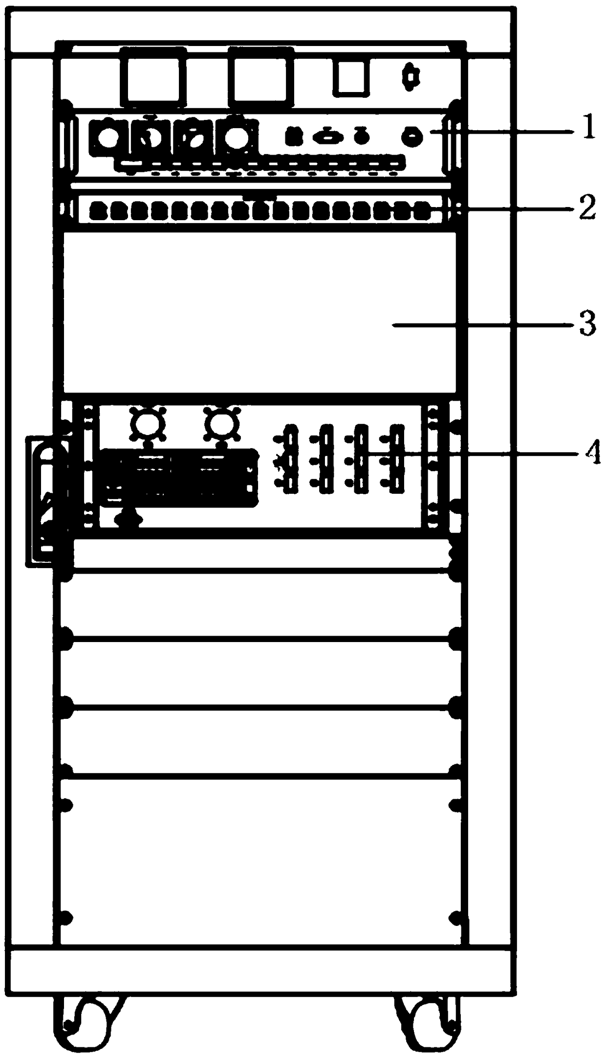
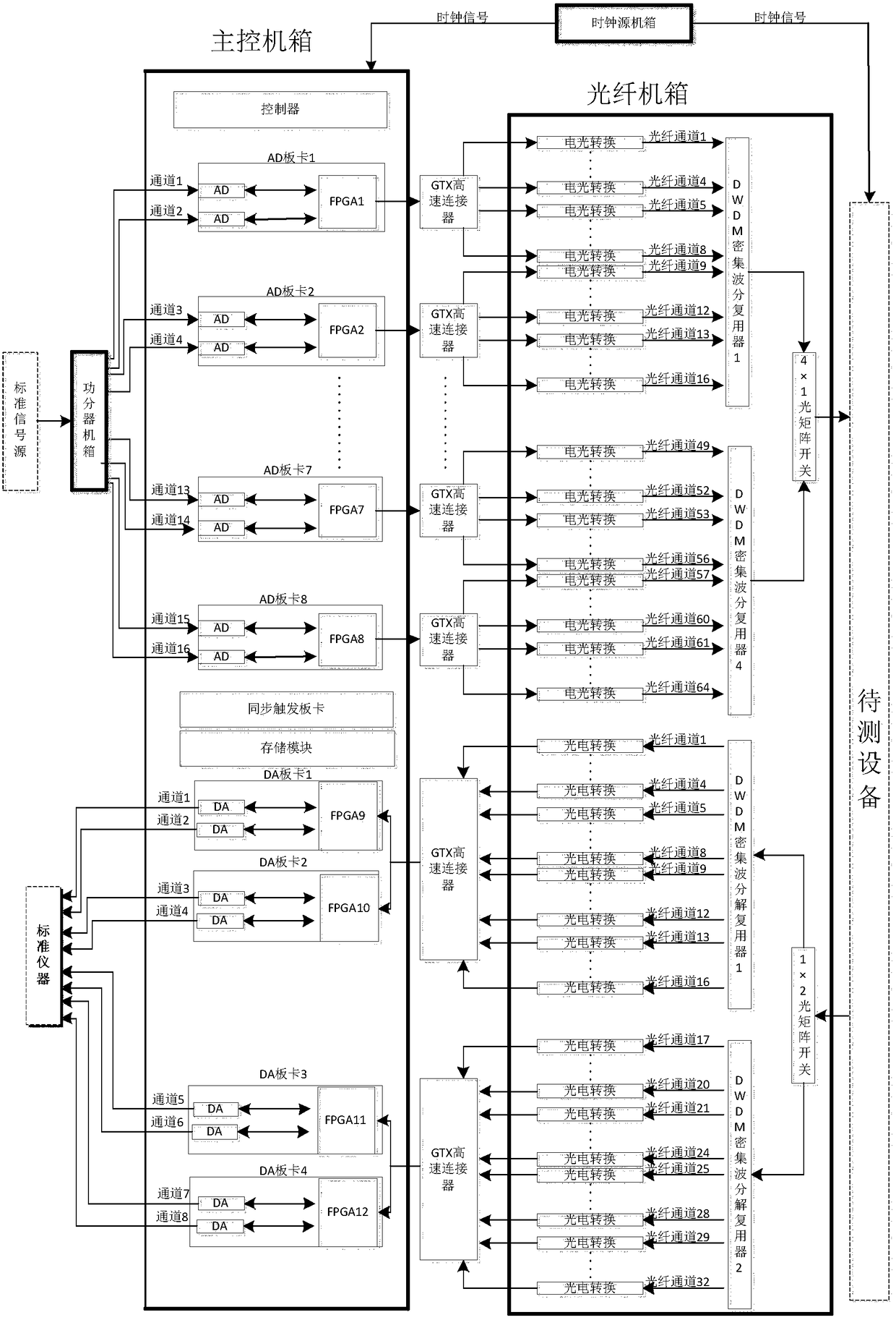
[0022] refer to figure 1 , figure 2 . In the embodiment described below, a multi-channel digital signal optical fiber transmission test equipment under test includes: fixed in the same cabinet, connected to the clock source chassis 1 of the equipment under test, power divider chassis 2, with a standard instrument interface The main control chassis 3 and the optical fiber chassis 4 connected to the equipment to be tested, the four chassis have independent functions, and are connected by radio frequency cables, data lines and optical fibers to complete the test of system indicators. When the signal to be tested is generated by a standard signal source, the 1-channel analog electrical signal sent by the standard signal source is divided into 16 channels of equal-amplitude and in-phase signals through the power divider chassis 2, and the power divider chassis 2 transmits the signal to the main control chassis 3 dual-channel AD board group, the AD board group converts the collec...


PUM


Abstract

The invention discloses a multi-channel digital signal optical fiber transmission test device, and aims to provide a test device with stable test performance and high reliability. The device is realized by the following technical scheme: one channel of analog electrical signals sent by a standard signal source is divided into 16 channels of equal-amplitude and in-phase signals through a power divider cabinet, the 16 channels of signals are transmitted to a dual-channel AD board group in a main control cabinet and converted into digital electrical signals, the digital electrical signals are sent to an optical fiber cabinet through GTX high-speed connectors connected with corresponding AD boards and converted into 64 channels of optical signals through respective electro-optical conversion module groups, the 64 channels of optical signals are combined into four channels of optical signals through four DWDM dense wavelength division multiplexers, the four channels of optical signals are combined into one channel of optical signals through an optical matrix switch, and the one channel of optical signals is sent to a device under test; and the device under test emits one channel of optical signals which is divided into two channels of optical signals through an optical matrix switch, the two channels of optical signals enter DWDM dense wavelength division multiplexers and are divided into 16 channels of optical signals of different wavelengths, the digital electric signals are converted into analog signals through digital-to-analog (DA) conversion, and the bit error rate is tested by a standard instrument.

Description

technical field [0001] The invention relates to a test equipment to be tested for multi-channel optical fiber signal transmission, especially suitable for testing and verifying equipment for multi-channel digital signal optical fiber transmission. Background technique [0002] Optical fiber communication is a communication technology that transmits information through optical fibers. At the sending end, the information is converted and processed into an electrical signal that is convenient for transmission. The light source is controlled by the electrical signal, so that the emitted optical signal has the characteristics of the electrical signal to be transmitted, thereby realizing the electrical-optical conversion of the signal. The optical signal is transmitted to the remote receiving end through optical fiber, and converted into an electrical signal by photodiode and other devices, thereby realizing the optical-electrical conversion of the signal. The electrical signal i...

Claims


Application Information

Patent Timeline
IPC IPC(8): H04B10/079
CPCH04B10/07953
Inventor 高鹏程李典王罡徐舒熊璐
Owner 10TH RES INST OF CETC
Why Eureka
Try Eureka