Plasma vacuum coating equipment with function of electrode and workpiece movement and using method

A vacuum coating and plasma technology, applied in the direction of gaseous chemical plating, metal material coating process, coating, etc., can solve the problems of poor uniformity and consistency of coating, easy pollution of chemical substances to the environment, and low sedimentation rate. Achieve the effects of improving uniformity and consistency, improving coating production efficiency, and increasing sedimentation rate

Inactive Publication Date: 2019-01-11
朱广智
View PDF3 Cites 8 Cited by
  • Summary
  • Abstract
  • Description
  • Claims
  • Application Information

AI Technical Summary

Problems solved by technology

[0003] The existing coating equipment and methods have the disadvantages of low sedimentation rate, low production efficiency, poor uniformity and consistency of the coating, poor waterproof, sweat-proof, moisture-proof, corrosion-re

Method used


Image

  • Plasma vacuum coating equipment with function of electrode and workpiece movement and using method

Examples


Example Embodiment

[0028] Example 1

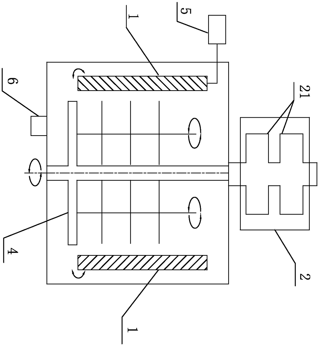
[0029] A plasma vacuum coating equipment for electrode and workpiece movement, used to coat PCBA, including moving electrode 1, vacuum exhaust device 2, plasma vacuum chamber 3, moving device for driving workpiece 4, plasma discharge source 5, air intake The pipeline 6, the plasma discharge source 5 and the vacuum exhaust device 2 are arranged outside the plasma vacuum chamber 3, and the moving electrode 1 and the moving device 4 for driving the workpiece are inside the plasma vacuum chamber 3.

[0030] The moving electrode 1 is arranged inside the cavity 3, and there is a pair in total. The electrode 1 reciprocates in the cavity 3 along the circumference close to the cavity.

[0031] The vacuum exhaust device 2 includes a vacuum pump 21 and an exhaust pipe. The vacuum pump 21 is divided into one stage and two stages. The vacuum exhaust device 2 is connected to the plasma vacuum chamber 3 through a pipe.

[0032] The plasma vacuum chamber 3 is a cylindrical chamber ...

Example Embodiment

[0043] Example 2

[0044] A plasma vacuum coating equipment for moving electrodes and workpieces, used to coat Bluetooth headsets, including moving electrodes 1, vacuum exhaust device 2, plasma vacuum chamber 3, moving device 4 for driving the workpiece, plasma discharge power source 5, inlet The gas pipeline 6, the plasma discharge source 5 and the vacuum exhaust device 2 are arranged outside the plasma vacuum chamber 3, and the moving electrode 1 and the moving device 4 for driving the workpiece are inside the plasma vacuum chamber 3.

[0045] The moving electrode 1 is arranged inside the vacuum cavity 3 and has two pairs of electrodes, and the electrodes reciprocate in a plane in the cavity 3.

[0046] The vacuum exhaust device 2 includes a vacuum pump 21 and an exhaust pipe. The vacuum pump 21 is divided into one level and two levels. The vacuum exhaust device 2 is connected to the plasma vacuum chamber 3 through a pipeline.

[0047] The plasma vacuum chamber 3 is a cubic chamber ...


PUM


Abstract

The invention discloses plasma vacuum coating equipment with the function of electrode and workpiece movement and a using method. The equipment comprises moving electrodes, a vacuum air exhausting device, a plasma vacuum cavity, a workpiece driving moving device, a plasma discharge source and an air inlet channel; the plasma discharge source and the vacuum air exhausting device are arranged on theexterior of the plasma vacuum cavity; and the moving electrodes and the workpiece driving moving device are arranged in the plasma vacuum cavity. The using method of the equipment comprises the following steps that the plasma vacuum cavity is vacuumized, and coating is conducted on a to-be-coated workpiece. According to the plasma vacuum coating equipment with the function of electrode and workpiece movement and the using method, the coating sedimentation rate and the coating production efficiency are improved by adopting a plasma-enhanced chemical vapor deposition method, the coating uniformity and consistency are improved, the protection effects such as water prevention, sweat prevention, moisture prevention, corrosion resistance and solvent resistance of a coating are improved, and theplasma vacuum coating equipment can be applied to various coating occasions such as PCBs, PCBAs, electronic products, electric appliance parts, electronic semi-products, metals, electronic components, semiconductors, integrated circuit boards and plastic products.

Description

technical field [0001] The invention relates to the technical field of plasma chemical vapor deposition, in particular to a plasma vacuum coating device and a use method for electrode and workpiece movement. Background technique [0002] Plasma Enhanced Chemical Vapor Deposition PECVD: It uses microwave or radio frequency to ionize the gas containing the constituent atoms of the film to form plasma locally, and the plasma is very chemically active and easy to react, depositing the desired film on the substrate . In order to enable the chemical reaction to proceed at a lower temperature, the activity of the plasma is used to promote the reaction, so this CVD is called plasma-enhanced chemical vapor deposition (PECVD). Experimental mechanism: The gas containing the constituent atoms of the film is locally formed into plasma by means of microwave or radio frequency, and the plasma is chemically active and easily reacts to deposit the desired film on the substrate. [0003] Th...

Claims


Application Information

Patent Timeline
IPC IPC(8): C23C16/50C23C16/458
CPCC23C16/4584C23C16/50
Inventor 朱广智
Owner 朱广智
Why Eureka
Try Eureka