Ion implanting machine and ion implanting method
An ion implanter and ion implantation technology, applied in the field of semiconductor equipment manufacturing, can solve problems affecting the performance of semiconductor devices, metal pollution, etc., and achieve the effect of reducing the generation of metal ions, preventing metal ions, and improving the yield rate
- Summary
- Abstract
- Description
- Claims
- Application Information
AI Technical Summary
Problems solved by technology
Method used
Image
Examples
Embodiment approach 1
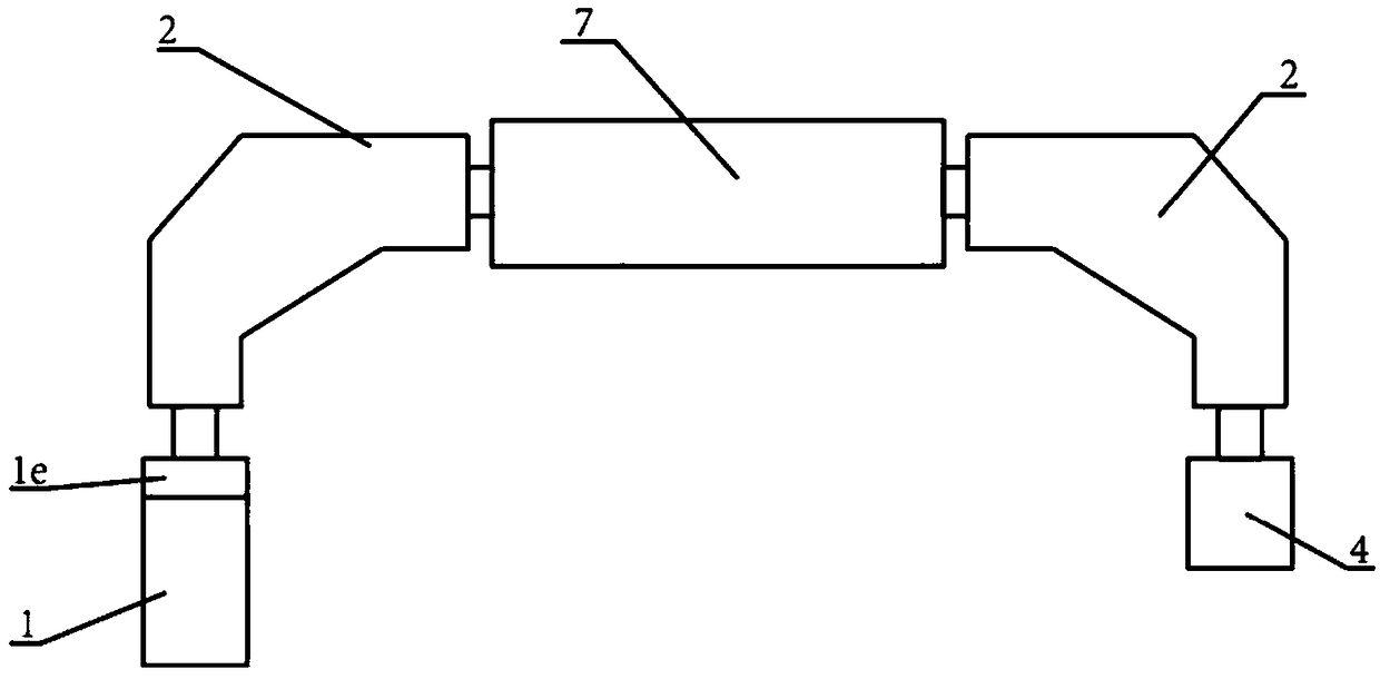
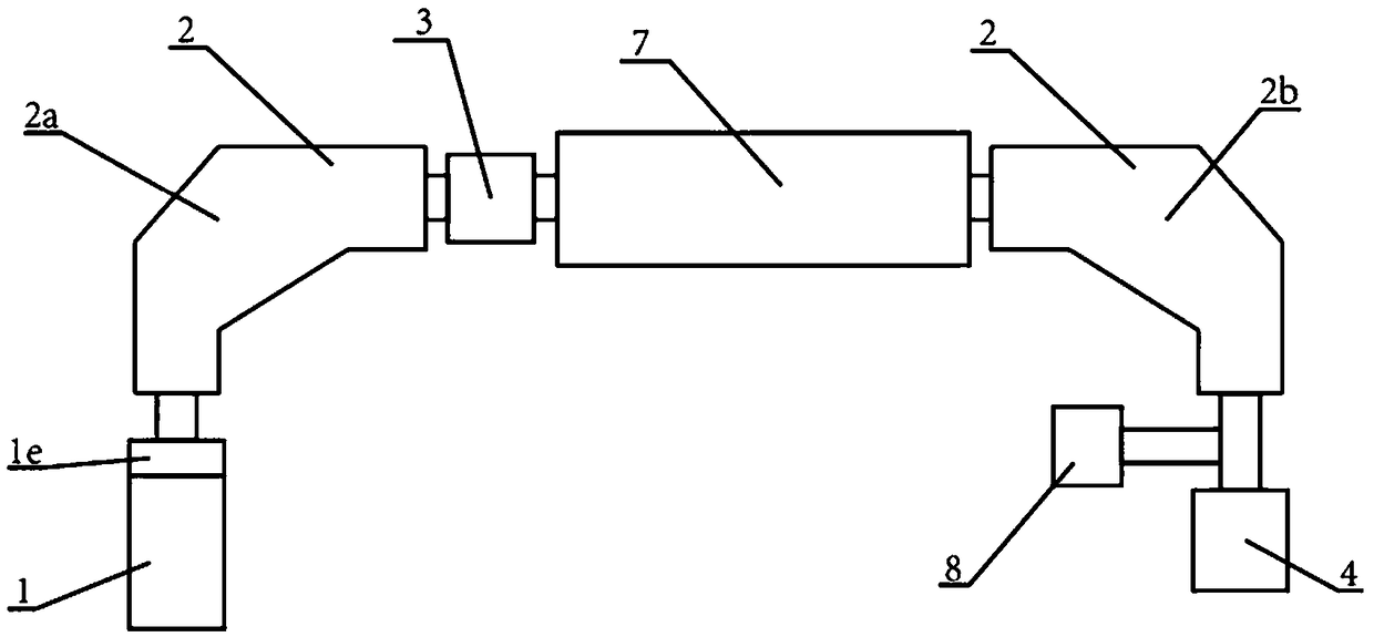
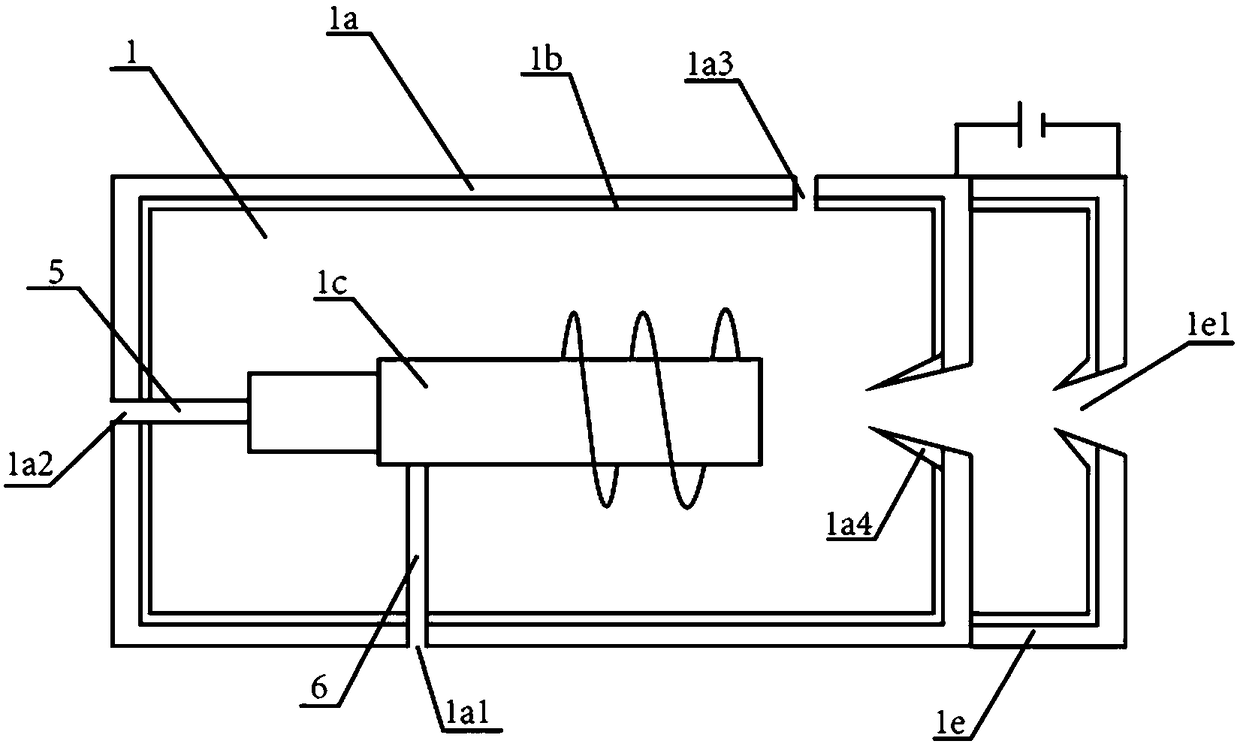
[0055] This embodiment provides an ion implanter, see figure 2 and image 3 As shown, it includes: ion source structure 1, analysis magnet 2, valence state conversion device 3 and process chamber 4; wherein, ion source structure 1 generates plasma through inductively coupled plasma technology and forms an ion beam; analysis magnet 2 is located in the ion The downstream of the source structure 1 is used to deflect the ion beam and select the ions in it to form an implanted ion beam; the valence conversion device 3 is connected to the analysis magnet 2, and can analyze the implanted ions after the analysis magnet 2 The valence state of the ions in the beam is converted; the process chamber 4 is arranged downstream of the valence state conversion device 3, and the wafer is placed in the process chamber 4, and the process chamber 4 is the place where the implanted ion beam bombards the wafer.
[0056] The ion implanter provided in this embodiment applies inductively coupled plas...
Embodiment approach 2
[0085] During the implantation process, the implanted ion beam bombards the wafer, causing positive ions to accumulate on the wafer, forming a large amount of charge on the wafer surface, changing the charge balance in the implanted ion beam, thereby affecting the dose of ion implantation . And because the surface of the wafer is usually formed with different patterns, the charged ions continuously scan the wafer during the ion implantation process, which may cause tip discharge on the wafer surface, thereby affecting the quality of ion implantation.
[0086] To solve this problem, a common method is to spray the wafer with electrons, that is, to spray low-energy electrons to the surface of the wafer. Specifically, before the implant ion beam is scanned onto the wafer surface, low-energy electrons are incorporated into the implant ion beam, thereby neutralizing the positive charge on the wafer surface and improving the effect of ion implantation.
[0087] In the prior art, th...
Embodiment approach 3
[0096] The third embodiment of the present invention provides an ion implantation method, see Figure 6-Figure 8 As shown, the ion implantation method according to the third embodiment of the present invention includes: an ion generation step, supplying energy to gas molecules and ionizing them, generating plasma by inductively coupled plasma technology and forming an ion beam; an ion selection step, ionizing The ion species in the beam is selected, the required ions are separated, and the implanted ion beam is formed; there is also a valence conversion step between the ion selection step and the ion acceleration step, and the implanted ion beam is bombarded by charged particles to make the implanted ion beam The valence state of the ions in the ion beam changes; the ion acceleration step, by applying a voltage to the implanted ion beam, adjusts the energy of the implanted ion beam; the ion implantation step, the implanted ion beam bombards the surface of the wafer, thereby per...
PUM
 Abstract
Description
Claims
Application Information
 - R&D
- Intellectual Property
- Life Sciences
- Materials
- Tech Scout
- Unparalleled Data Quality
- Higher Quality Content
- 60% Fewer Hallucinations
Browse by: Latest US Patents, China's latest patents, Technical Efficacy Thesaurus, Application Domain, Technology Topic, Popular Technical Reports.
© 2025 PatSnap. All rights reserved.Legal|Privacy policy|Modern Slavery Act Transparency Statement|Sitemap|About US| Contact US: help@patsnap.com


