An rc-igbt device based on junction termination

A junction terminal and device technology, applied in the field of semiconductor power devices, can solve problems such as affecting the use of RC-IGBT devices, increasing IGBT manufacturing costs, etc., and achieve the effect of eliminating the Snapback phenomenon

Active Publication Date: 2021-08-13
希力微电子(深圳)股份有限公司
View PDF7 Cites 0 Cited by
  • Summary
  • Abstract
  • Description
  • Claims
  • Application Information

AI Technical Summary

Problems solved by technology

However, the IGBT is only a unidirectional conduction device, and an anti-parallel diode is required to withstand the reverse voltage during application, which increases the manufacturing cost of the IGBT and brings difficulties such as packaging and welding.
[0003] In order to solve this problem, the IGBT capable of reverse conduction is called RC-IGBT (reverse-conducting insulated-gate bipolar transistor, reverse conduction insulated gate bipolar transistor) has gradually begun to be used in the electronic field, such as Figure 1~2 Shown are the schematic diagrams of the structure of the traditional groove gate RC-IGBT device and the traditional planar gate RC-IGBT device respectively. The traditional RC-IGBT device realizes the integration of IGBT and diode by introducing the N-type collector into the P-type collector. ; But in the forward conduction, the introduction of the N-type collector region will make the current-voltage output curve of this traditional RC-IGBT show a snapback phenomenon. The Snapback phenomenon is more obvious under low temperature conditions, which seriously affects the RC-IGBT. -Use of IGBT devices

Method used


Image

  • An rc-igbt device based on junction termination
  • An rc-igbt device based on junction termination
  • An rc-igbt device based on junction termination

Examples


Embodiment Construction

[0017] The technical solution of the present invention will be further described in detail below in conjunction with the accompanying drawings, but the protection scope of the present invention is not limited to the following description.

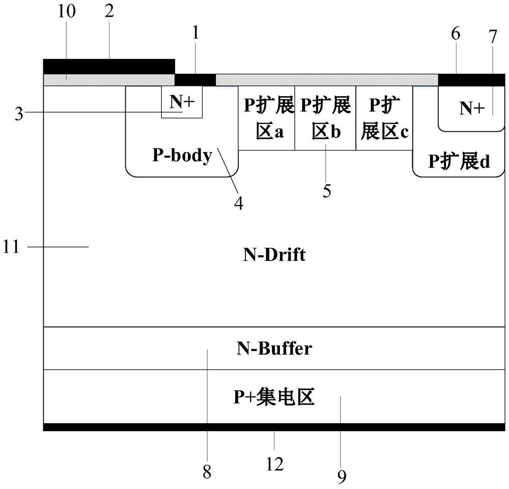
[0018] Such as image 3 As shown, an RC-IGBT device based on a junction terminal includes a P+ type collector region 9, an N-drift region 11, and an N-type buffer zone 8 between the P+ type collector region 9 and the N-drift region 11;

[0019] The P+ type collector region 9, the N-drift region 11 and the N-type buffer region 8 are simultaneously in the device active region and the device terminal region;

[0020] The device active region also includes an emitter structure and a gate structure located on the surface of the N-type drift region 11;

[0021] The device terminal region also includes a P-type extension region 5 located on the surface of the N-drift region and an N+ type collector region 7 located in the P-type extension region....


PUM


Abstract

The invention discloses an RC-IGBT device based on a junction terminal. Based on a traditional RC-IGBT device structure, a junction terminal extension area (5) is arranged in the junction termination area, and an N+ type collector area is arranged in the junction termination extension area. (7), connect the bottom P-type collector with the N-type collector of the junction terminal area with an interconnection line. ) The PN junction formed by ) is reverse-biased, so that the device directly works in the IGBT mode and does not work in the MOSFET mode, so there will be no Snapback phenomenon during the conduction process; in the freewheeling diode mode, the P-type base (4), The P-type junction terminal extension area (5) and the N+ type collector area (7) form a PN diode, and when the voltage drop exceeds the turn-on voltage of the PN diode, the device is turned on and can conduct current. Therefore, the RC-IGBT based on the junction terminal provided by the present invention completely eliminates the Snapback phenomenon in the forward conduction process of the traditional RC-IGBT.

Description

technical field [0001] The invention belongs to the field of semiconductor power devices and relates to an insulated gate bipolar transistor, in particular to an RC-IGBT device based on a junction terminal. Background technique [0002] IGBT (Insulate Gate Bipolar Transistor, Insulated Gate Bipolar Transistor) not only has the advantages of high input impedance, low control power, simple drive circuit, and high switching speed of MOSFET, but also has the advantages of high current density and saturation voltage of bipolar power transistor. It has the advantages of low power consumption and strong current handling ability, so it is widely used in induction cooker, UPS uninterruptible power supply, automotive electronic igniter, three-phase motor inverter, welding machine switching power supply and other products as power switch tube or power output tube, the market prospect very broad. IGBT products are very ideal switching devices in the field of power electronics. It combi...

Claims


Application Information

Patent Timeline
Patent Type & Authority Patents(China)
IPC IPC(8): H01L29/739H01L29/06
CPCH01L29/0696H01L29/7395
Inventor 黄海猛刘远成胡浩
Owner 希力微电子(深圳)股份有限公司
Why Eureka
Try Eureka