
Vibrating straw pulverizer facilitating blanking

A straw pulverizer, vibrating technology, applied in agricultural machinery and tools, cutting equipment, applications, etc., can solve the problems of poor feeding, easy blockage, and difficulty in meeting the needs of use, so as to improve the crushing efficiency and facilitate feeding , Solve the effect of poor cutting

Inactive Publication Date: 2019-01-15
临泉县隆源农业有限公司
View PDF0 Cites 6 Cited by
  • Summary
  • Abstract
  • Description
  • Claims
  • Application Information

AI Technical Summary

Problems solved by technology

[0003] When straw is recycled, the straw needs to be crushed. The existing straw crusher has poor feeding and is easy to block, which is difficult to meet the needs of use.

Method used


Image

  • Vibrating straw pulverizer facilitating blanking
  • Vibrating straw pulverizer facilitating blanking
  • Vibrating straw pulverizer facilitating blanking

Examples


Embodiment 1

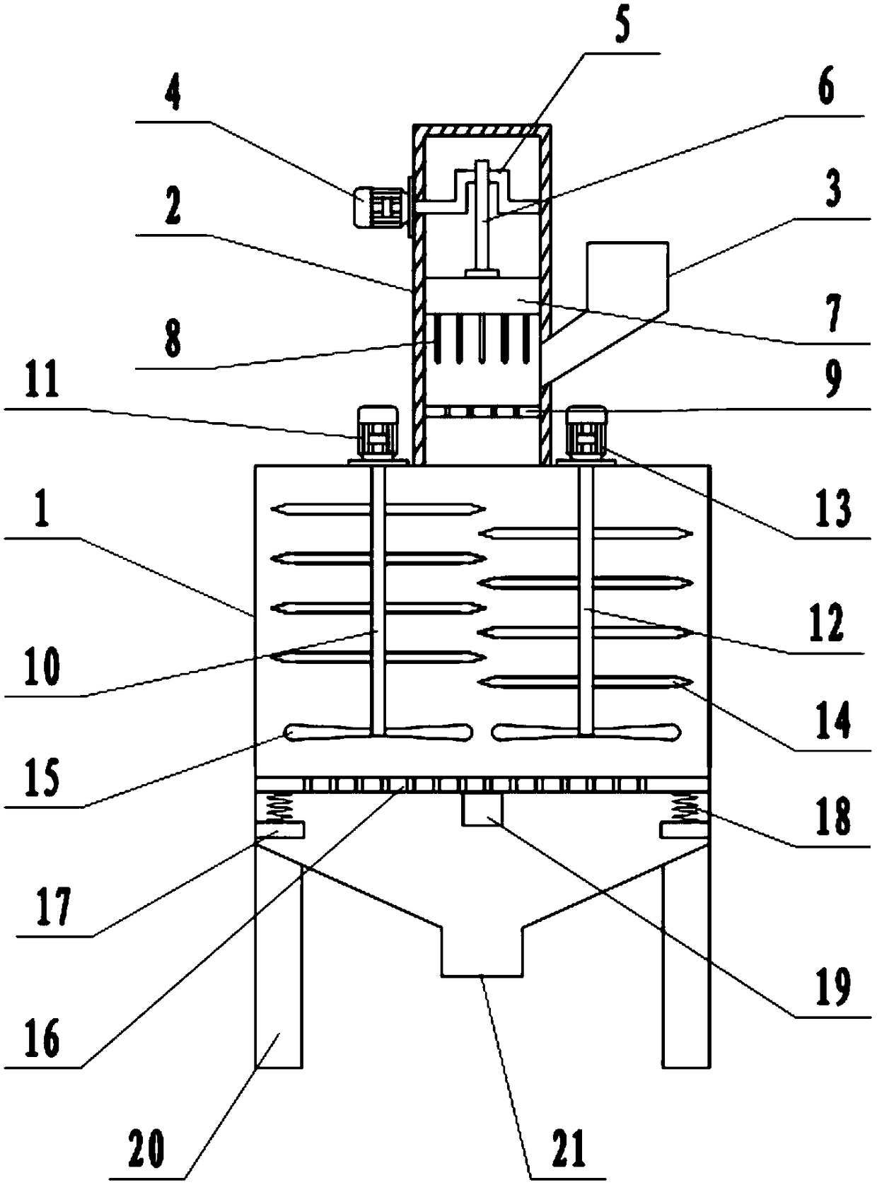
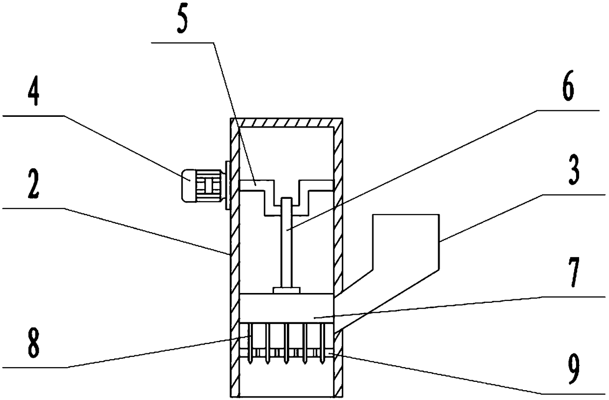
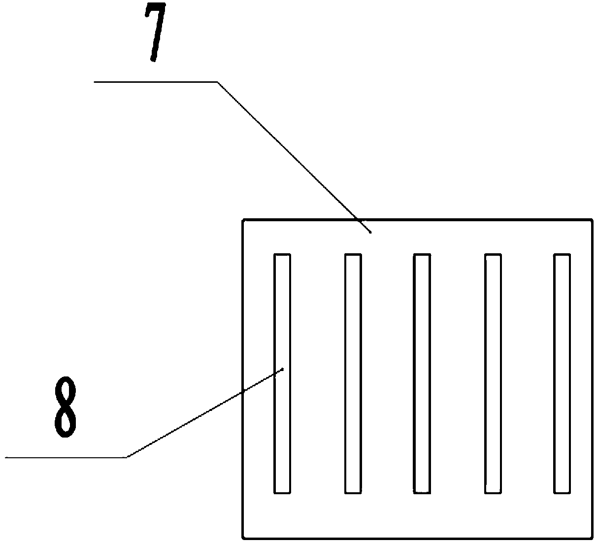
[0022] see Figure 1-3 , in an embodiment of the present invention, a vibrating straw grinder that is convenient for unloading includes a crushing bin 1, a feeding port 3, a left crushing shaft 10, a right crushing shaft 12, a crushing blade 14 and a discharge port 21, and the crushing bin 1 The upper surface of the lower material bin 2 is installed, the lower material bin 2 is connected with the crushing bin 1, the right side wall of the lower material bin 2 is installed with the feeding port 3, the feeding port 3 is connected with the lower material bin 2, and the left side of the lower material bin 2 The side wall is fixedly connected with a blanking motor 4, the shaft extension end of the blanking motor 4 is fixedly connected with a crankshaft 5, the other end of the crankshaft 5 is rotationally connected with the right side wall of the blanking motor 4, and the journal of the crankshaft 5 is sleeved with a The connecting rod 6, the inside of the blanking motor 4 is provid...

Embodiment 2

[0025] On the basis of Embodiment 1, a vibrating sieve plate 16 is provided below the stirring blade 15, and the vibrating sieve plate 16 is slidably connected with the inner wall of the crushing bin 1. The inner wall of the warehouse 1 is fixedly connected, the upper surface of the fixed frame 17 is fixedly connected with a spring 18, the top of the spring 18 is fixedly connected with the lower surface of the vibrating sieve plate 16, and the middle part of the lower surface of the vibrating sieve plate 16 is also fixedly connected with a vibration motor 19, Start the vibrating motor 19 to drive the vibrating sieve plate 16 to vibrate up and down, so that the crushed stalks pass through the vibrating sieve plate 16 and fall to the bottom of the crushing bin 1.


PUM


Abstract

The invention discloses a vibrating straw pulverizer facilitating blanking, comprising a pulverizing bin, a feeding port, a left pulverizing shaft, a right pulverizing shaft, a pulverizing blade and adischarging opening, wherein a blanking bin is installed on the upper surface of the pulverizing bin, the left side wall of the blanking bin is fixedly connected with a cutting motor, the shaft end of a blanking motor is fixedly connected with a crankshaft, a connecting rod is connected to a journal of the crankshaft, and a movable block is arranged inside the blanking motor. The lower end of theconnecting rod is hinged to the upper surface of the movable block, and the lower surface of the movable block is distributed with a plurality of blanking cutting blade s, and a grid plate is arranged below the cutting blades. Straws are initially cut by the blanking cutting blades, and the cutting blades apply downward force on the straws to allow the straws to be dropped into the pulverizing bin after passing through the grid plate to prevent the straws from accumulating inside the blanking bin, which facilitates the straw blanking. A left pulverizing shaft and a right pulverizing shaft arearranged, the straws are crushed by the pulverizing blade, so that the straws are pulverized smash more fully and the pulverization efficiency is improved.

Description

technical field [0001] The invention relates to an agricultural machine, in particular to a vibrating straw pulverizer which is convenient for unloading. Background technique [0002] Straw is the general term for the stems and leaves (ears) of mature crops. Usually refers to the remaining parts of wheat, rice, corn, potato, rapeseed, cotton, sugar cane and other crops after harvesting seeds. More than half of the photosynthetic products of crops exist in straw, which is rich in nitrogen, phosphorus, potassium, calcium, magnesium and organic matter, etc. It is a multi-purpose renewable biological resource, and straw is also a roughage. It is characterized by high crude fiber content and lignin. Although lignocellulose cannot be utilized by pigs and chickens, it can be absorbed and utilized by ruminant cattle, sheep and other livestock. [0003] When recycling straw, the straw needs to be pulverized, and the existing straw pulverizer does not feed smoothly, is easy to be b...

Claims


Application Information

Patent Timeline
Patent Type & Authority Applications(China)
IPC IPC(8): A01F29/02A01F29/08A01F29/09A01F29/10
CPCA01F29/005A01F29/02A01F29/08A01F29/09A01F29/10
Inventor 殷笑笑
Owner 临泉县隆源农业有限公司
Learn More