
Magnetic roll structure for magnetic trolley

A magnetic roller and trolley technology, applied to motor vehicles, auxiliary devices, auxiliary welding equipment, etc., can solve the problems of waste of resources, difficult maintenance, high replacement costs, etc., to reduce labor intensity, improve maintenance efficiency, and save resource consumption. Effect

Pending Publication Date: 2019-01-18
上海华威焊割机械有限公司
View PDF0 Cites 4 Cited by
  • Summary
  • Abstract
  • Description
  • Claims
  • Application Information

AI Technical Summary

Problems solved by technology

[0005] The current disadvantages of this structure are: 1. The materials used in the current magnetic steel block are easy to lose magnetism. With the increase of the number of uses, the magnetic attraction force is greatly weakened; 2. The magnetic steel is relatively large in size and heavy in weight, which increases the The load of the drive motor, in addition, the magnetic steel uses rare metals, which wastes a lot of resources; 3. The copper worm gear is also relatively large, and it is a wearing part of the transmission mechanism, which costs a lot to replace after wear and causes a waste of resources ;4. This structure is difficult to maintain and the maintenance cost is high. When the copper worm wheel is replaced, since the magnetic roller is directly connected to the copper worm wheel, there are individual differences in the size of the copper worm wheel, which will easily lead to changes in the overall concentricity. Requires secondary processing to ensure roller concentricity

Method used


Image

  • Magnetic roll structure for magnetic trolley
  • Magnetic roll structure for magnetic trolley
  • Magnetic roll structure for magnetic trolley

Examples


Embodiment

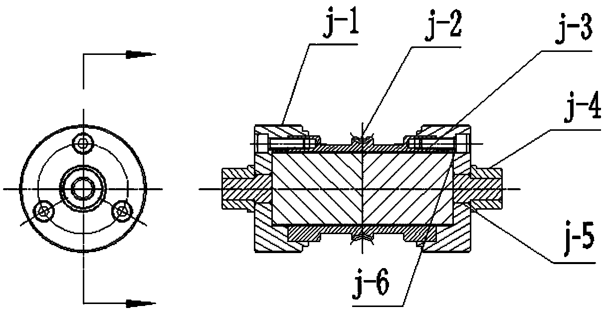
[0024] see Figure 5 and Image 6 , the present invention provides a magnetic roller structure for a magnetic trolley, comprising a roller shaft 5 and bearing sleeves 11 with lubricating oil holes sleeved at both ends of the roller shaft 5, a copper worm wheel 7 is fixed in the middle of the roller shaft 5, It is clamped and fixed by the left worm wheel pressing cap 6, and it also includes a roller assembly symmetrically arranged at both ends of the roller shaft 5. The roller assembly includes an outer roller 1, an inner spacer, and Cover 2 and inner roller 4, the outer spacer 3 is concentrically arranged outside the inner spacer 2, and a magnetic steel block 8 is arranged between the inner spacer 2 and the outer spacer 3, and the outer spacer, magnetic steel The block 8 and the inner spacer 2 are clamped and fixed between the outer roller 1 and the inner roller 3, and the outer roller 1 and the inner roller 4 are fixedly connected by internal and external threads, welding or...


PUM


Abstract

A magnetic roll structure for a magnetic trolley comprises a roller shaft and a bearing sleeve, a copper worm wheel is fixed in the middle sleeve of the roller shaft, and also comprises a roller assembly symmetrically arranged at both ends of the roller shaft; the roller assembly comprises an outer roller sleeve, an inner spacer sleeve and an inner roller sleeve sequentially sleeved on the rollershaft; Fe-B, any one or combination of a rare earth permanent magnetic Sm2CO17 sinter ferrite alloy and an aluminum-nickel-cobalt alloy AlNiCo, As that magnetic steel is replace, it is not easy to lose magnetism in use, the volume of the magnetic steel block is reduced, This reduces the driving force of the motor, As that labor intensity is reduce, the structure of the copper worm wheel is chan, so that the roller wheel is not fixedly connected with the copper worm wheel, the concentric degree doe not change after the copper worm wheel is replaced, secondary machining is not required to correct the copper worm wheel, the maintenance cost is reduced, the weight of the copper worm wheel is reduced, and the energy consumption is reduced.

Description

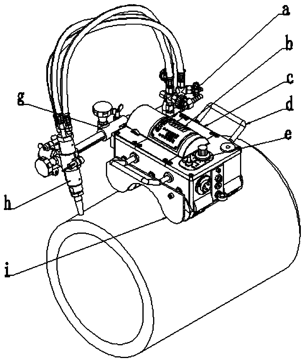
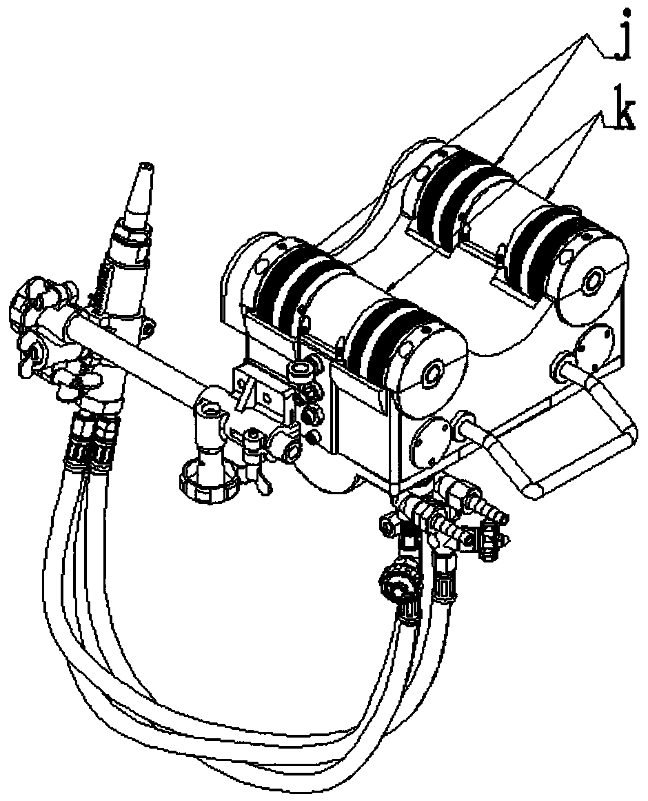
technical field [0001] The invention relates to a walking trolley device for cutting or welding on pipes or steel plates, in particular to a magnetic roller structure for a magnetic trolley. Background technique [0002] The magnetic trolley is mainly used for cutting and welding of pipelines or flat plates in petroleum, natural gas, shipbuilding, chemical industry, engineering construction, etc. [0003] Such as figure 1 and figure 2 As shown, the magnetic trolley is mainly composed of gas circuit and gas distribution system a, drive system including gear box b, trolley body with portable handle d, control panel e, cutting torch clamping adjustment device and drive system g, gas cutting Cutting torch h, heat shield i, magnetic roller j and dust cover constitute k, where the fuselage c is the skeleton of the whole device, used to carry various components on the device, and the drive system g provides power for the whole device; the control panel e is used to control the ...

Claims


Application Information

Patent Timeline
Patent Type & Authority Applications(China)
IPC IPC(8): B62D57/024B23K37/00B23K37/02
CPCB62D57/024B23K37/00B23K37/02
Inventor 潘帆蒋继良施文彬肖怀勇
Owner 上海华威焊割机械有限公司
Learn More